Most everyone who uses a wheelchair knows there are realistic limits to the distance that can be traveled. Heavy use of hands, arms and shoulders for self propulsion risks irreversible damage.
Taking walks and sojourns with spouse and friends. Shopping. Giving the dog a good walk. These activities are not realistically possible for most wheelchair users.
The solution for many is a dedicated powered mobility device like a scooter or a powered wheel chair. Most of these are heavy and not easily transported. And they lack the ability to use an often convenient combination of self propulsion and battery power. Large 24” diameter wheel chair tires traverse over small curbs better than smaller scooter wheels and a strong rider can temporarily input nearly twice as much wheel torque as a small electric motor in a scooter.
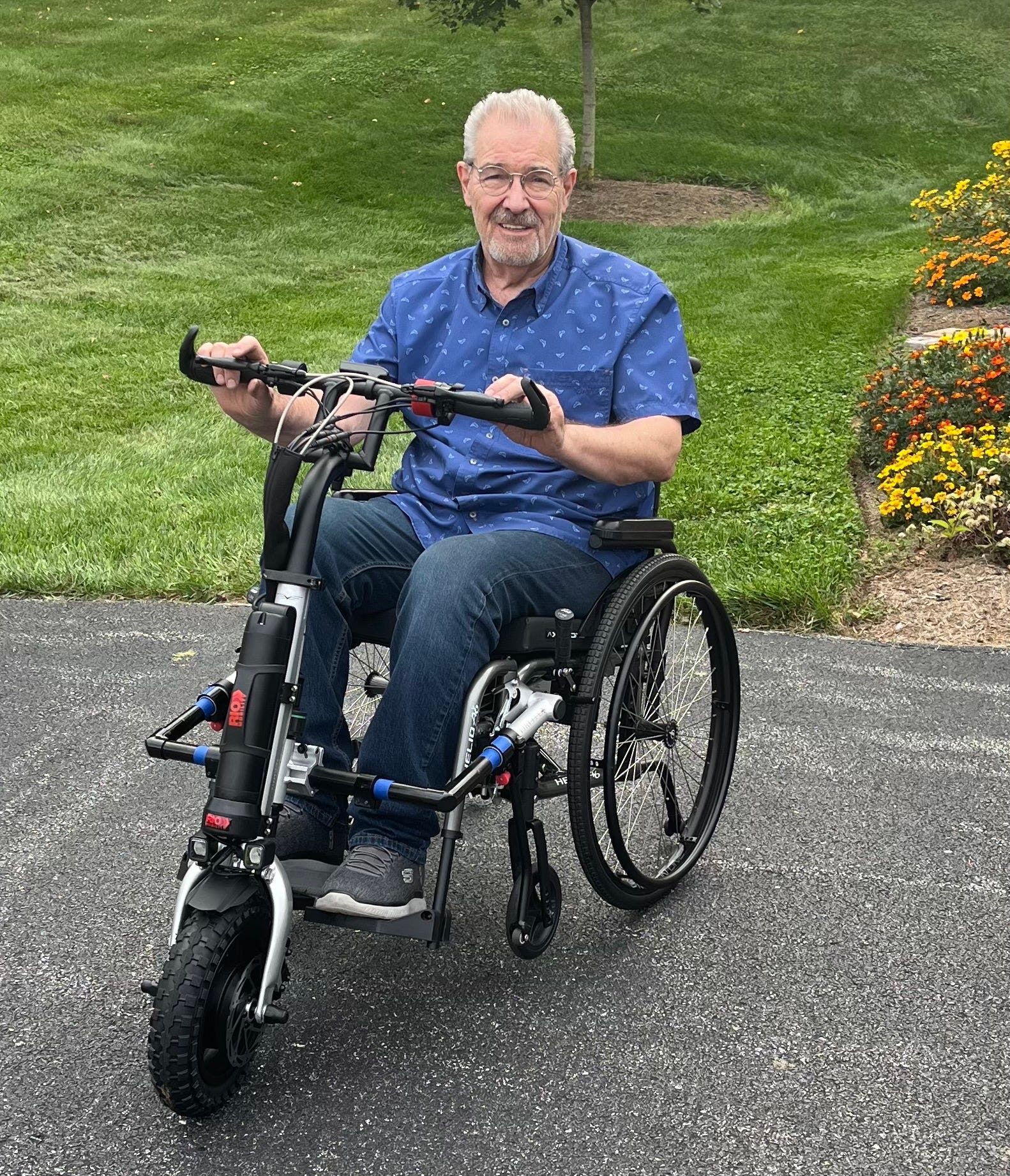
A very practical solution is to add a power assist device to a wheelchair. There are three general categories: 1) A motor incorporated in the main wheel chair wheels: 2) A motorized device that attaches to the rear of the chair; and 3) A motorized device that attaches to the front of the chair making it essentially a tricycle.
I found the third option to be the most attractive. The first two options generally are the most expensive. And, since the tricycle power assist provides handlebars, there are familiar hand controls for throttle and braking. No Bluetooth wifi required. They are easily steered and can be driven with one hand. They eliminate the problem of small front caster wheels being unable to roll over small obstacles, uneven pavement or soft surfaces. The only two disadvantages are: 1) A single front powered wheel loses traction going up steep inclines- this can be overcome by driving in reverse; and 2) The device adds considerable length to the chair.
Here is my “story” of adapting a RioMobility Firefly 2.5 to my folding Motion Composites Helio A6 wheelchair.
My Firefly Project:
\
One major appeal of the Firefly was that it attached to the wheelchair using a two part latching mechanism. The stationary “post” attaching permanently to the chair; the latch with a closing lever part of the Firefly. (Somewhat similar to the way an automobile door is connected to the car chassis.) This system seemed superior for a folding wheelchair.
Attaching a Firefly to most “rigid” wheelchairs is quite straightforward. Install the tubing clamps with anchor posts on the front of the frame up near the top bend. Video on YouTube shows clearly.
On a “folding” chair like my Motion Composites Helio A6, the install is more challenging as the attachment of the tubing clamps interferes with the folding/detachable footrests.
To make room for the tubing clamps I removed the footrest latch. This required a substantial redesign of the footrest attachment.
Footrest redesign
I removed the factory latching mechanism that was inserted into the lower tube of the footrest assembly.
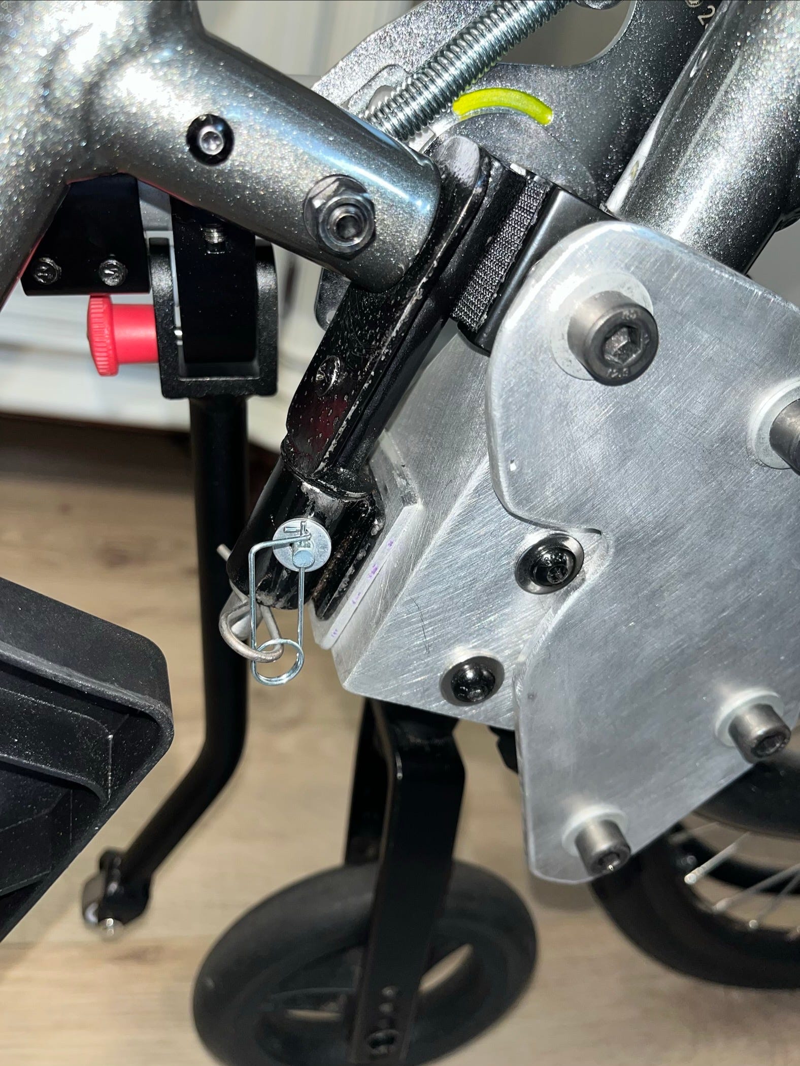
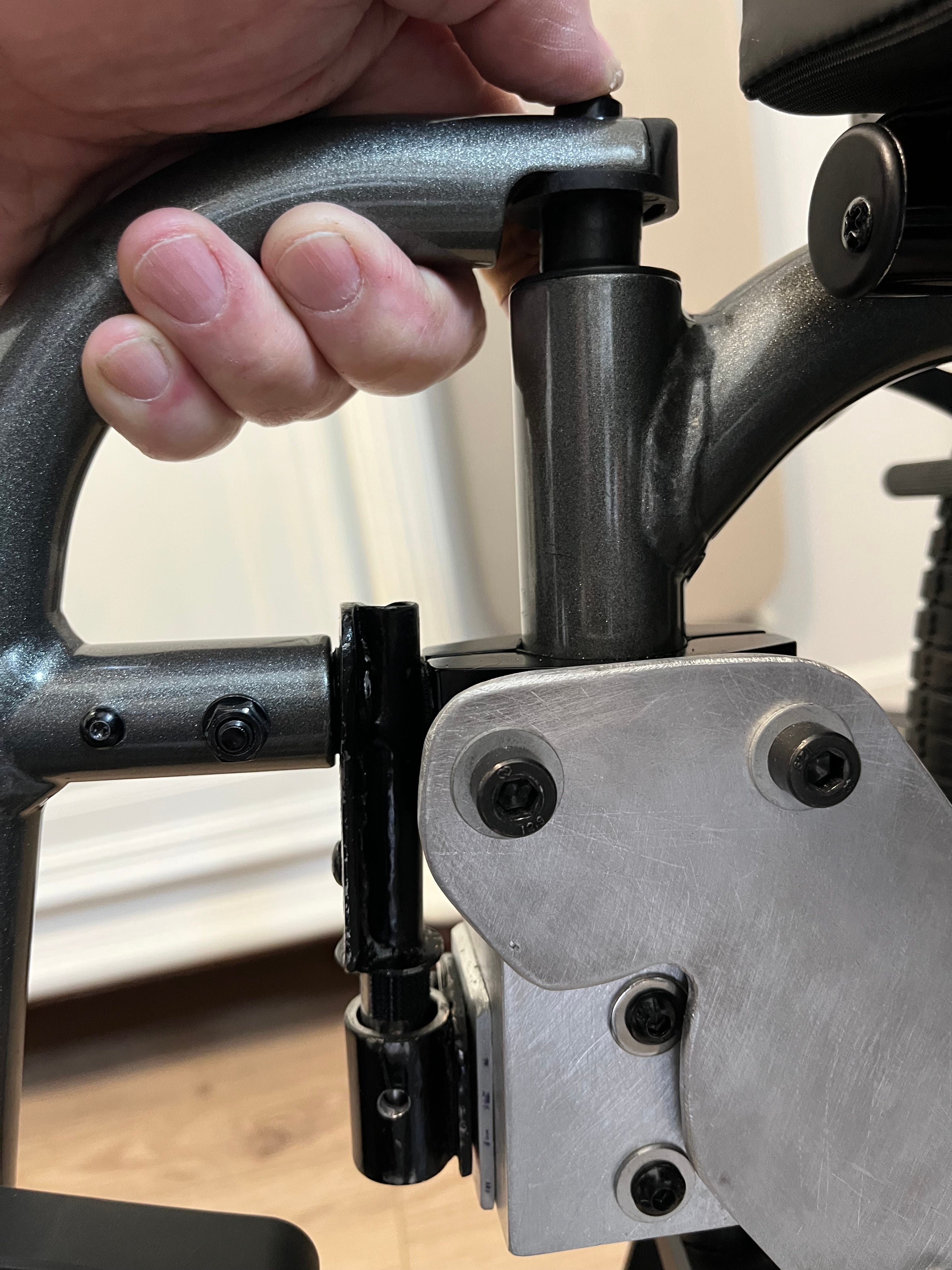
Then fabricated a welded/brazed bracket with: 1) a steel tube inserted into the footrest horizontal tube; 2) a vertical “male” steel tube; and 3) a “female” steel tube to receive the male tube. (The horizontal steel tube was made from ½ NPT pipe which was threaded into a 1 ¼ x 1/8 steel flat bar, with the vertical tube made from ½ OD tubing with a 3/8 solid rod inserted-all welded/brazed together. The steel tube and rod was purchased on Amazon, the bar from Tractor Supply. The horizontal steel tube was then inserted into the footrest tube- a “shim” made from 0.030” HDPE (from a milk jug) provided a slid “press” fit.)
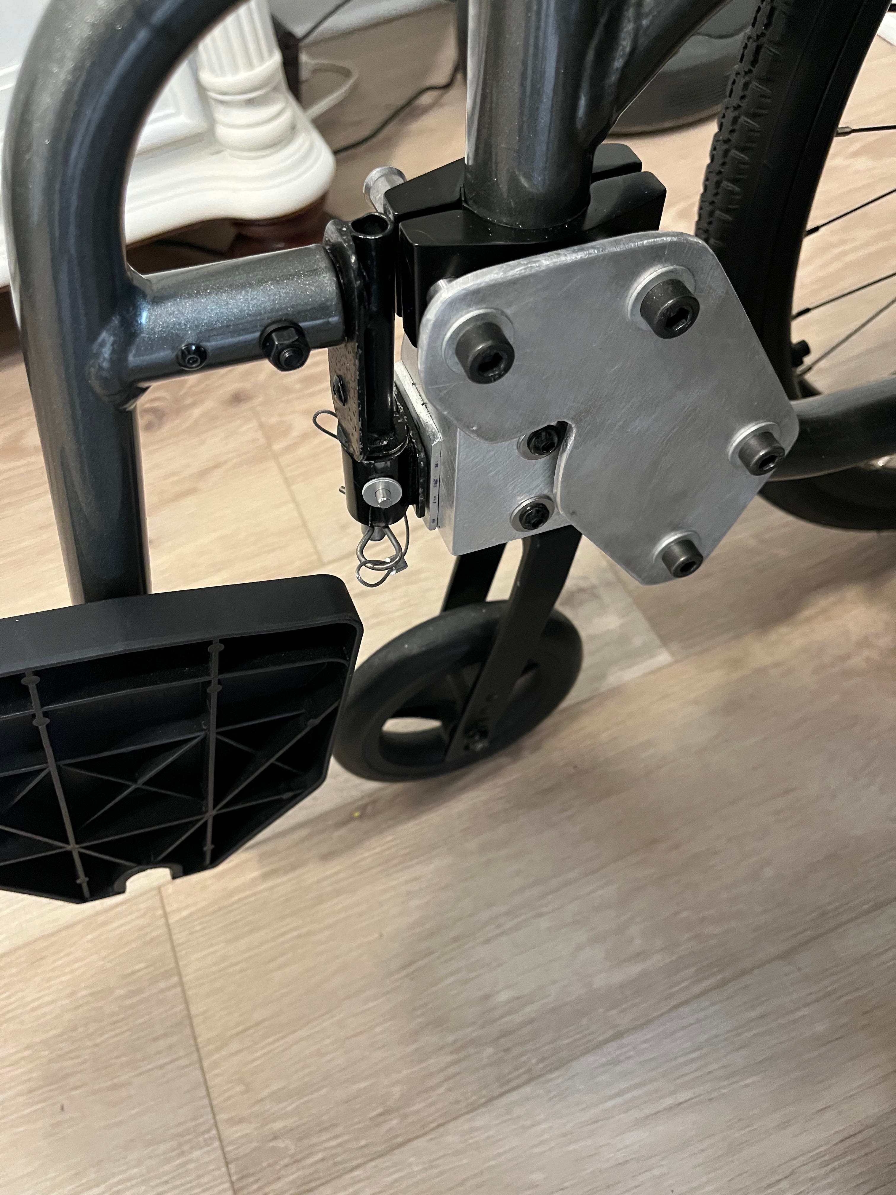
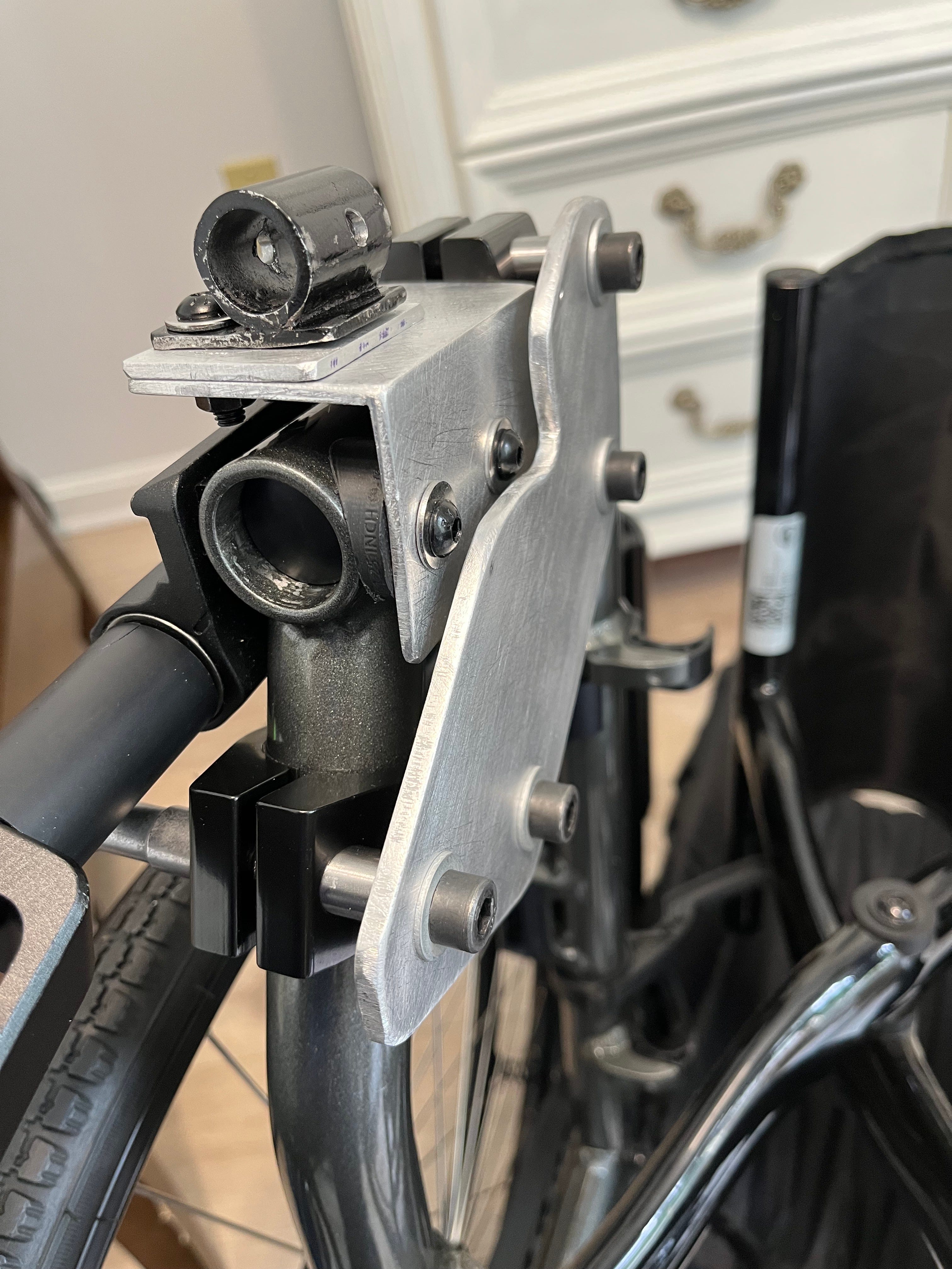
Mounting the female part of the mechanism to the chair was possible because of a unique design used by Motion Composites on the Helio A6 to mount the front caster wheels. They use a steel cylinder inserted into the frame that is tapped for M6 threads. They conveniently tapped both sides of the cylinder with unused threads available on the opposite side of the tube from the caster mounting. I mounted a 2×2×1/8 aluminum angle piece to the wheelchair frame using these holes and incorporated 1.125” tubing to flat adapter washers. The aluminum angle was purchased from Tractor Supply. The female steel tube is mounted to this bracket with sufficient adjustability to properly align with the male tube attached to the footrest.
To “anchor” the footrest once inserted into the top receptacle and the female tube, I drilled the female and male tubes to receive a 3/16” clevis pin. This required a high degree of precision to minimize “play” in the footrest once inserted and installed.
Redesign of attachment to frame
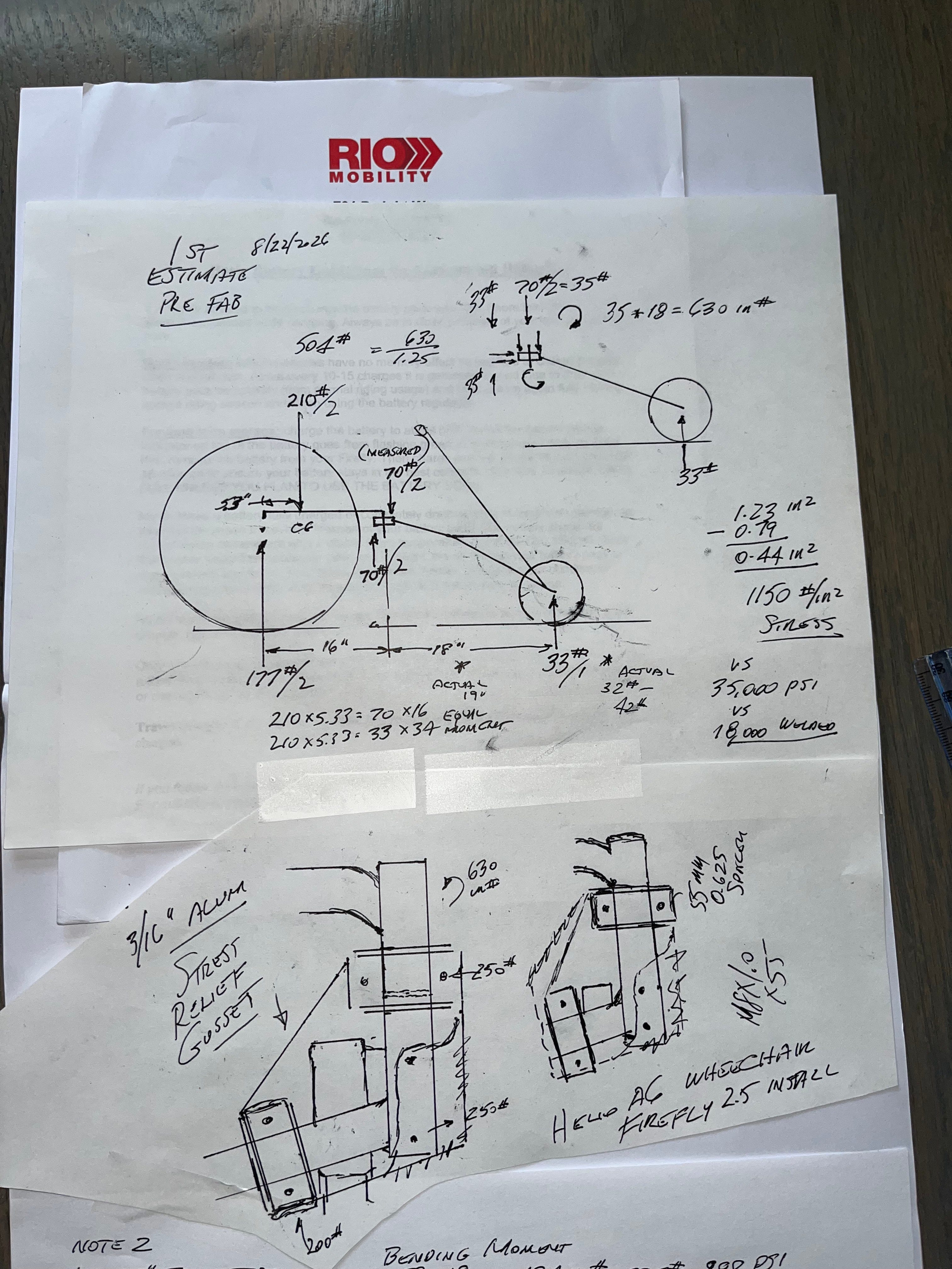
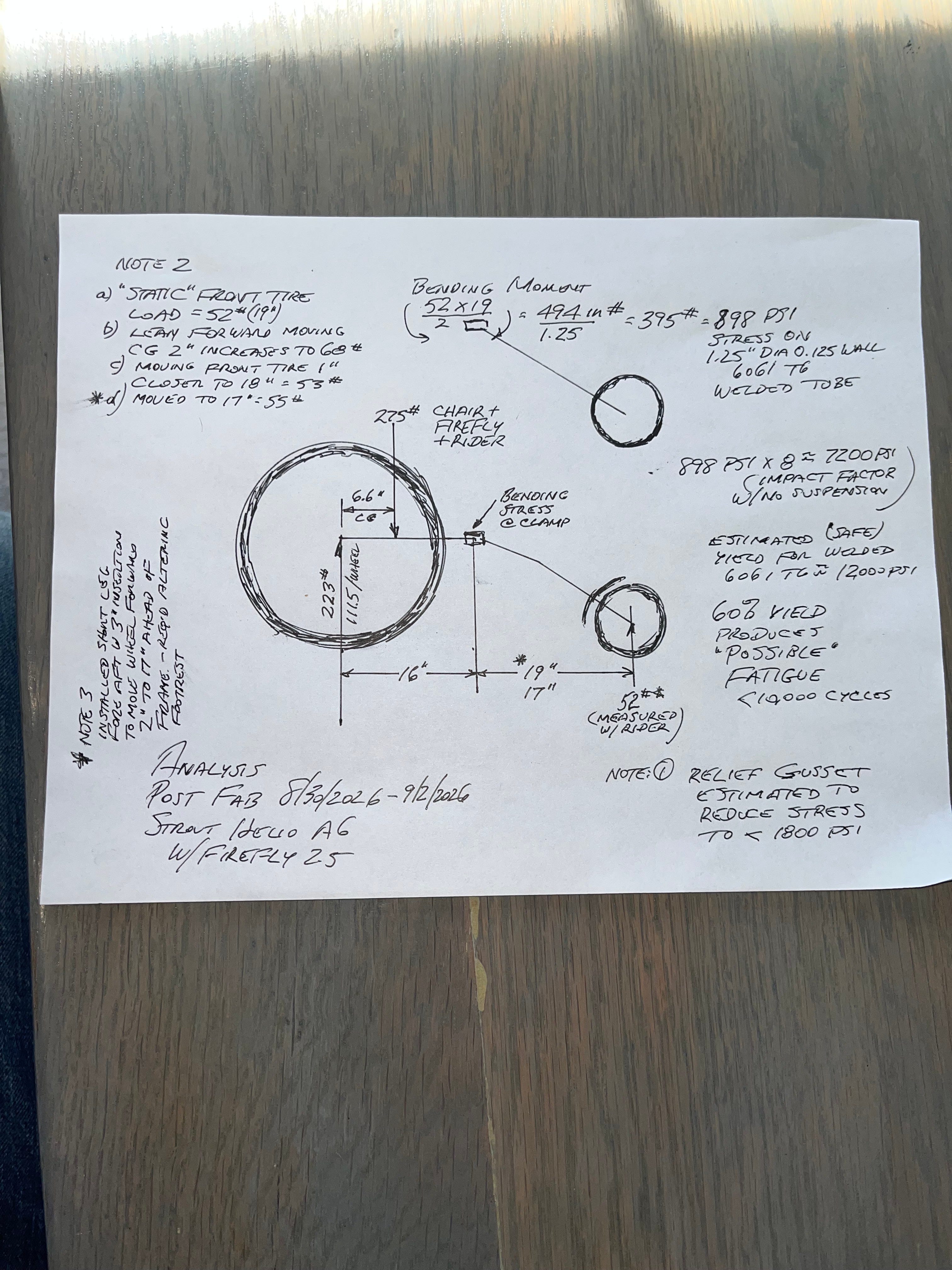
My preliminary analysis of the stress induced by the Firefly onto the wheel chair frame convinced me that some reinforcement and redesign was advisable.
Aluminum has a finite fatigue life and even though the Helio A6 frame is made from very strong 6061 T6 aluminum, the mounting location is very close to two welded joints. In addition the frame was drilled to mount the footrest latch exactly where the tubing clamp mounts. My analysis convinced me that it was unwise to use just one clamp.
The fatigue endurance limit for 6061 T6 aluminum is around 14000 psi for 100,000+ cycles plus the wheel chair on solid rubber tires has no suspension and therefore the frame is subjected to serious shock loading when driven outdoors on sidewalks and streets. (8x on the frame and 5x on the Firefly) The stress on the Firefly components is a bit less as the tire is pneumatic. In addition, the strength of aluminum at and near welded joints is less predictable than the tubing itself. So caution is called for.
I ordered a second tubing clamp kit ($100) and mounted the second clamp on the lower frame. I connected the clamps with a reinforcement plate made from 3/16 aluminum bought on eBay. To provide alignment I fabricated (8) spacers made from ½ “ tubing. (same as the tubing used for the footrest) Making these spacers would have been easy with a lathe, but I managed to use a hack saw, finishing with a very long and tedious use of a file to get a precise 0.625” height with two parallel surfaces. It took me nearly an hour to finish each spacer.
The threads for the special tubing clamps used on the Firefly are M8×1mm fine thread. I special ordered the alloy screws 60mm long from McMaster Carr.
The addition of the reinforcement plates and the second clamp reduces the stress significantly by more than half with the additional benefit of reducing the necessary clamping force to eliminate slippage. There is no longer any risk of fatigue failure or failure from over stressing the tube at the edge of the clamp.
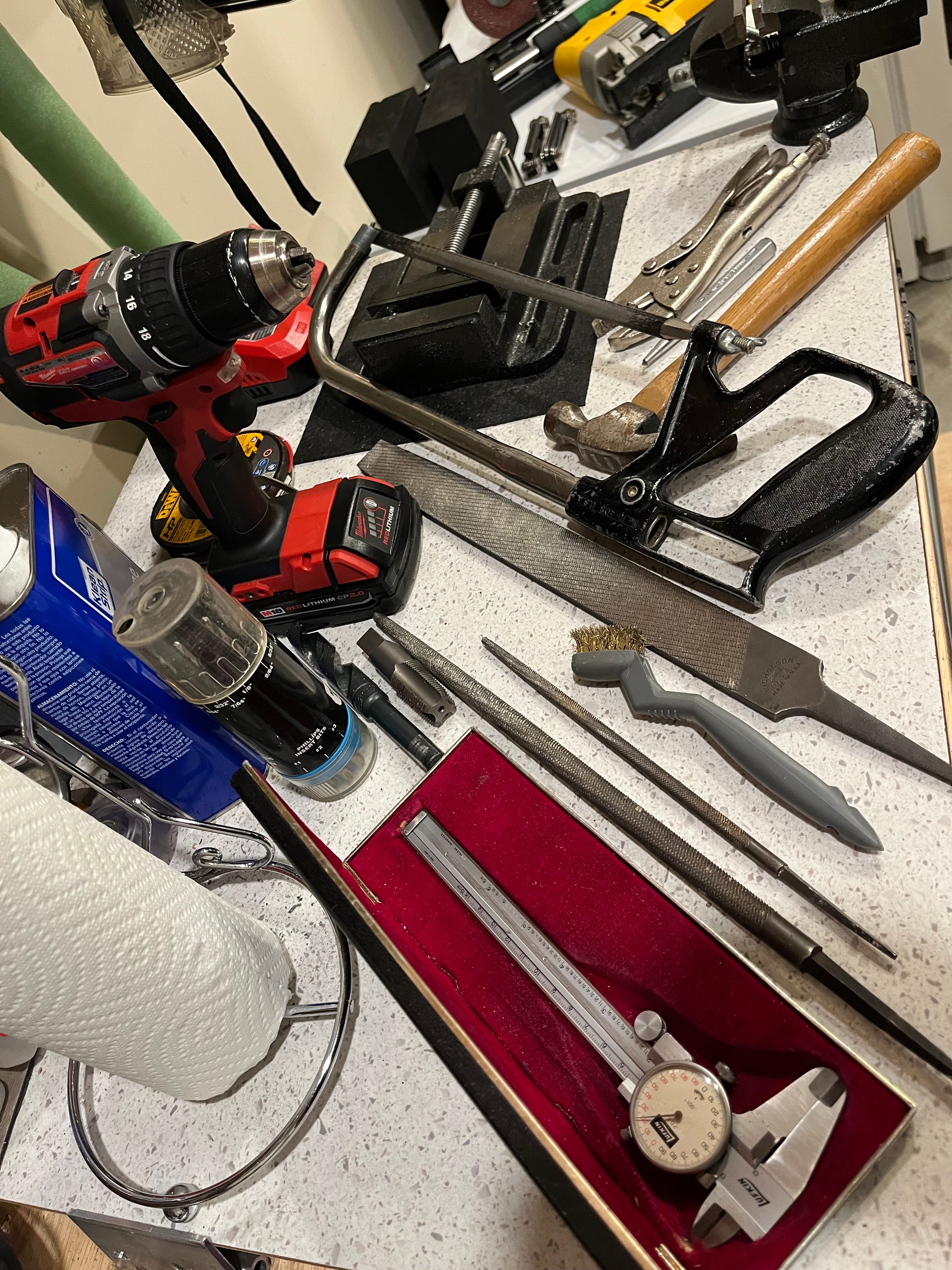
Cutting the steel was slow with a hacksaw. I used a jig saw for the aluminum. Drilling was done with a hand held drill. Filing and sanding was extremely tedious.
Once everything was filed, sanded and fitted-ready to assemble and connect the Firefly. (YouTube videos describe this process very well.)
A review of my weight calculations including the weight of the chair and the Firefly indicated a weight of 52 pounds on the front tire. Possible to increase to 68 pounds by leaning forward. This was confirmed using a weight scale and by my first one mile test drive.
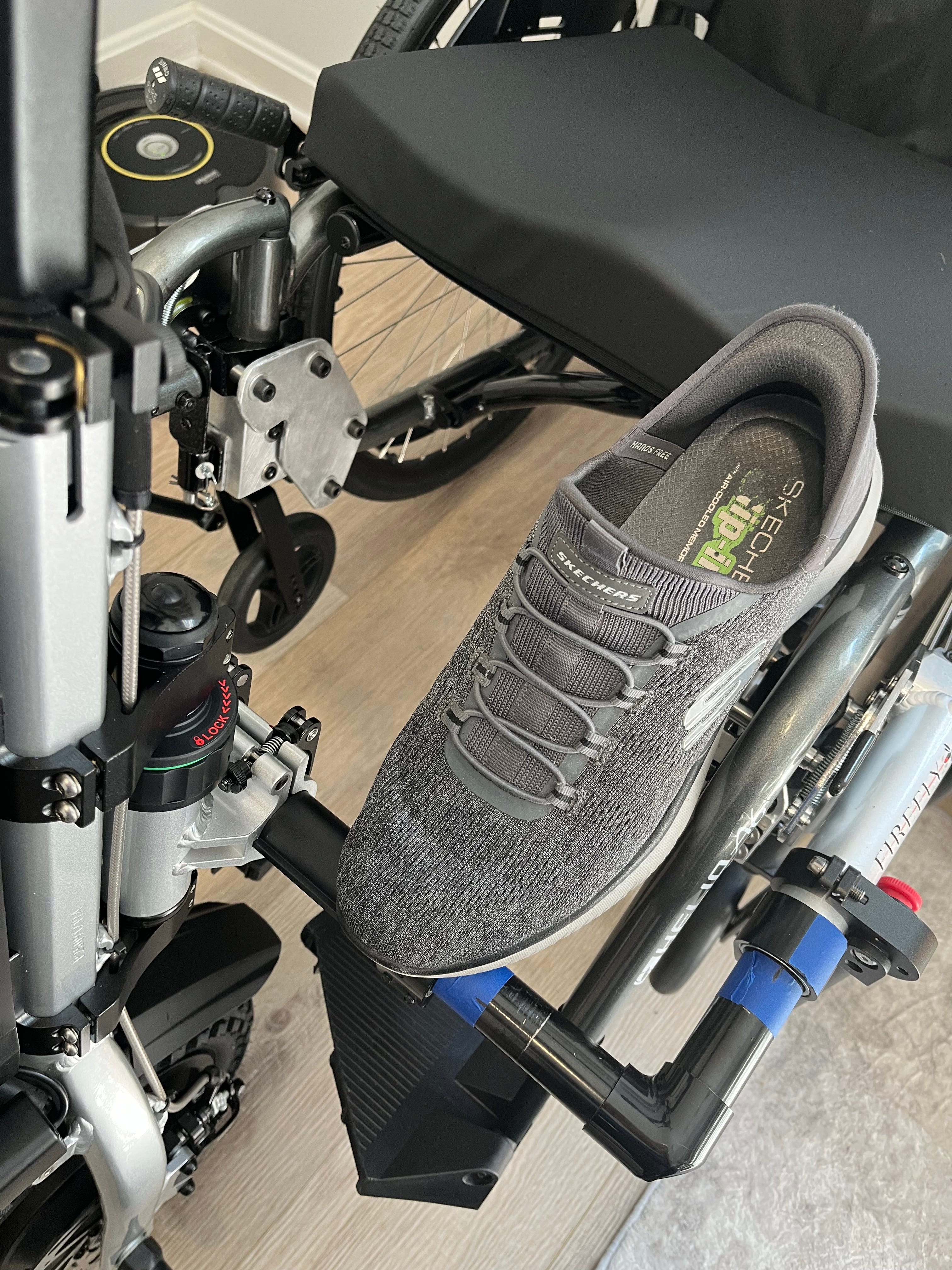
Moving the tire closer to the chair by 1-2 inches or so only changed weight on tire by 1-2 pounds. So my first thought was to provide enough space for the footrest “platforms” and for my foot to comfortably enter. The Firefly “u-bar” has a 5.25” leg and a 7.25” leg. To gain the fore-aft clearance I wanted, I placed the longer leg in the fore-aft position.
The first “road” test was very good, as expected. Ability to navigate 2%-3% grade was acceptable but steeper hills required using reverse for traction.
(An ADA compliant wheelchair ramp is just under 5 degrees or 1:12= 8% slope. It should be noted that the brakes work better when going down hill so going uphill on a ramp or steep slope is theoretically safer in reverse since brakes could hold the chair. But, it should also be noted that a three wheel vehicle is less stable going up hill in reverse. The Firefly 2.5 is rated to produce enough power to navigate the ramp in reverse at slow speeds but the ability to ascend the ramp is highly reliant on good traction-clean dry surface with a high coefficient of friction. I tested the Firefly on asphalt with a 7 degree slope and experienced wheel spin going forward- and slowly slid backwards with brakes fully applied. Ascended in reverse easily but power used reached the unit’s max rated 350 watts. But, I would not attempt any steep incline in excess of a properly constructed ramp incline of 1:12 and at that level would also avoid any incline that did not have guard rails and hand rails for safety. The Firefly equipped wheel chair has a high center of gravity-the rider is advised to shift body weight when encountering turns or inclines.)
Average watts during the road test used (as indicated on the digital dash readout) was less than 100 watts so reasonable to expect 2 hours from the 252 watt-hour battery-about 6 miles range for my weight at walking speed. (Power range 1 is perfect 2.5-3 mph for dog walking) Moving up to power range 2 increases speed to above 5mph but power draw almost doubles and range would be cut in half.
The unit is very maneuverable. I am able to “drive” it inside our condo thru all the doorways and hallways.
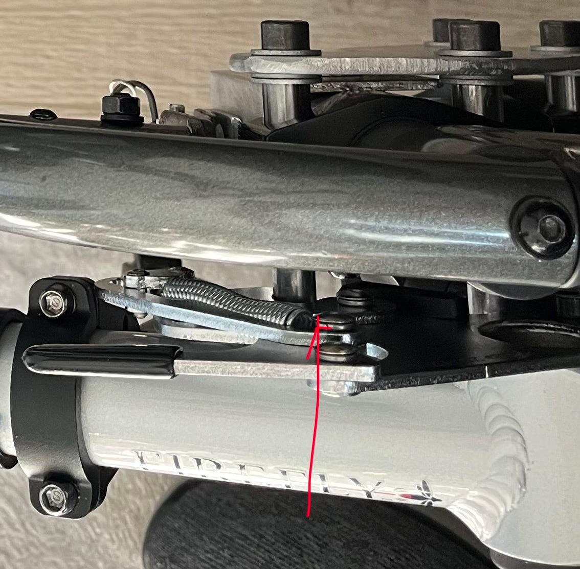
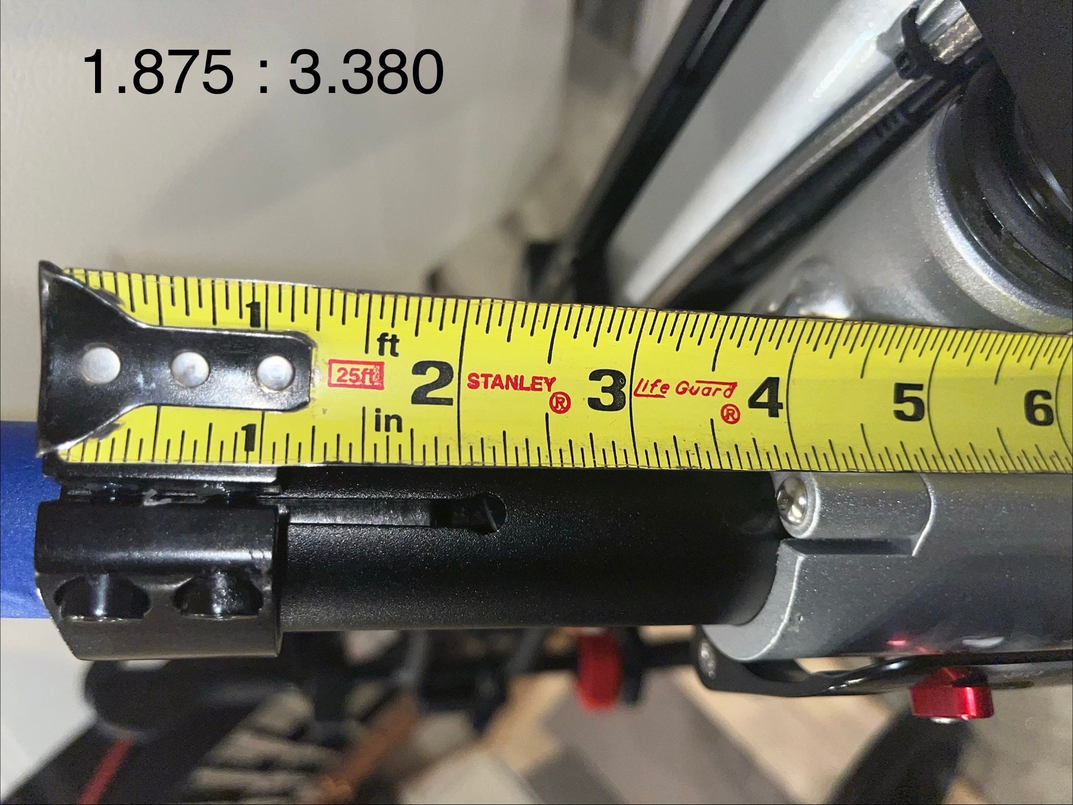
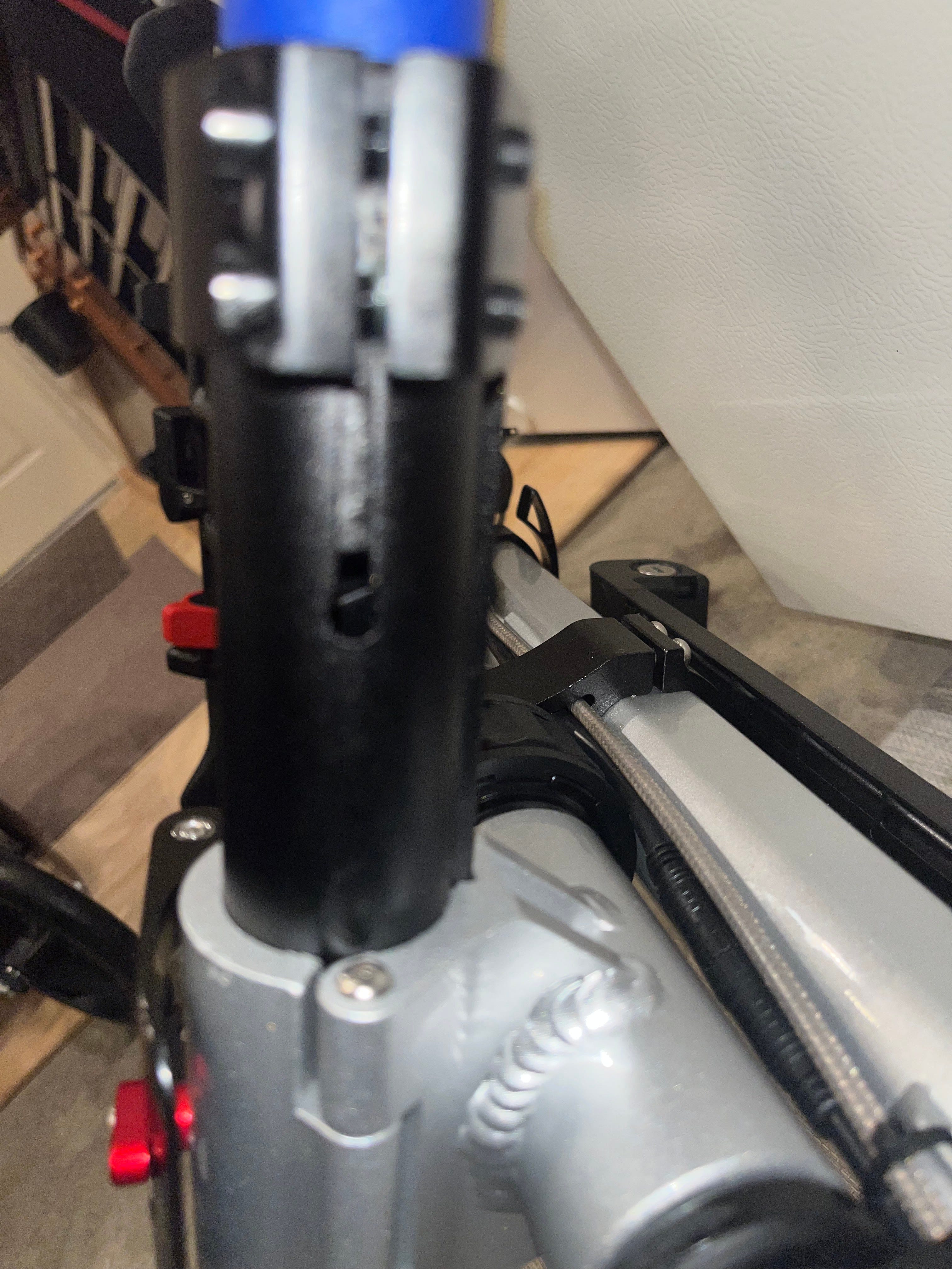
After my test drive, I reviewed the total assembly and discovered that the 5.25” leg of the ubar installed transverse did not extend past the slot in the clamped tube. This is a big red flag as good design requires slotted tube assemblies to have the inside tube extend past the slot by more than 0.75” to avoid excess stress and tube deformation. Plus, the 1.875” overlap was substantially less than the 2-2.5 x tubing OD good practice recommendation. So, I disassembled and reassembled with the longer 7.25” leg in the transverse direction and set the bar with 3” overlap on the fore-aft leg. This made the transverse tubing assembly very strong. This also reduced the “foot and knee” clearance and the Firefly “extension” by 2”.
Here is a stress analysis of the final assembly spec on the Firefly components. The stress on the transverse tubing connections is particularly complicated because of the slot and that the tubes are subjected to BOTH bending and torsion. Properly assembled, the Firefly is well engineered.
A bit more difficult to get my feet thru the opening.
To make clearance for the footrest folding platforms, I sawed them cutting of a significant part of the inside corners.
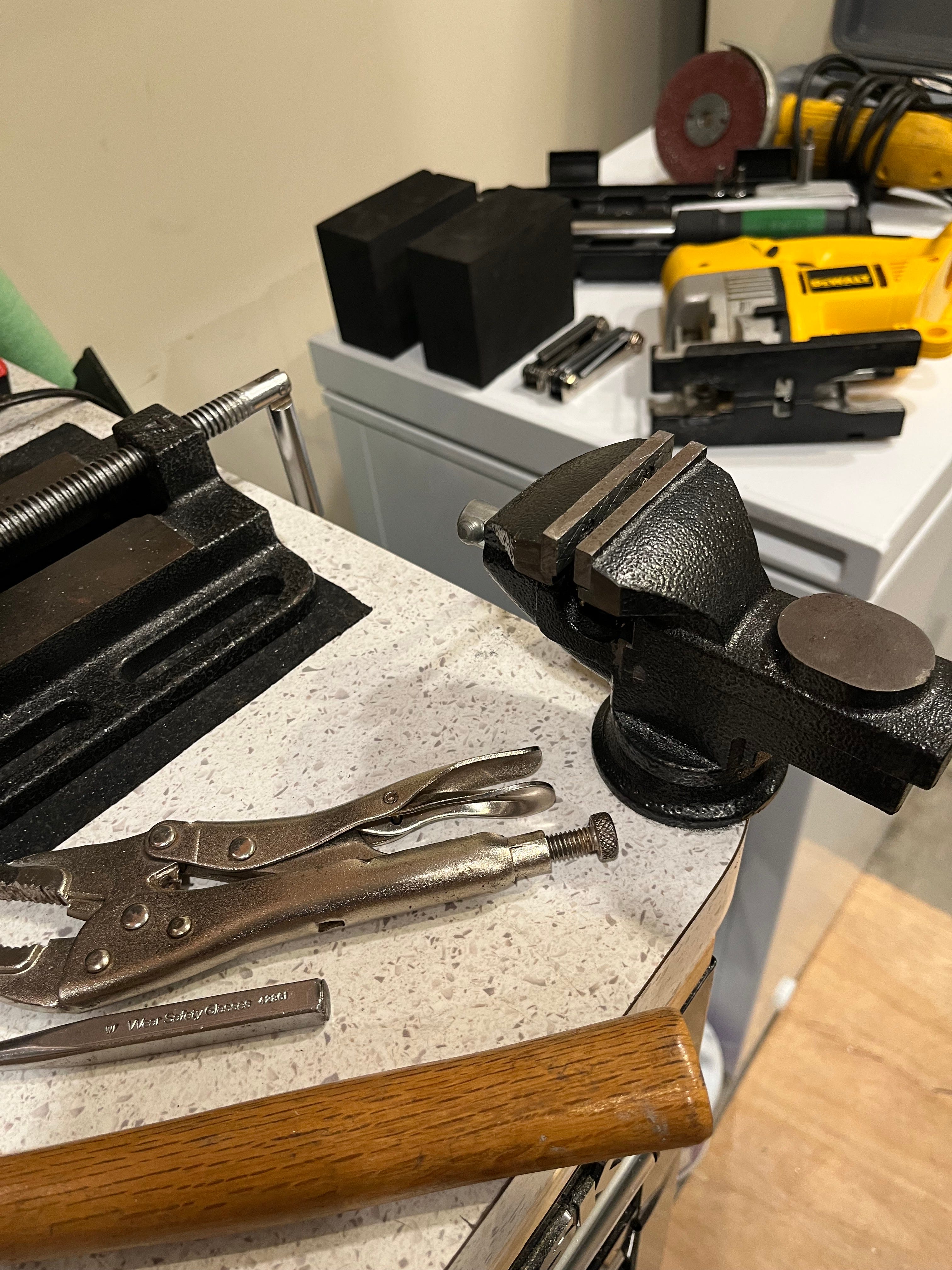
This project would have been much easier with typical professional machine shop tools like a lathe, vertical mill, drill press, powered saws for cutting steel. I used very primitive tools in my condo garage where I only have a tiny vice. The most important tool was my dial calipers. I was measuring with 0.001-0.003 tolerances-achieving probably 0.005 tolerances in most cases.
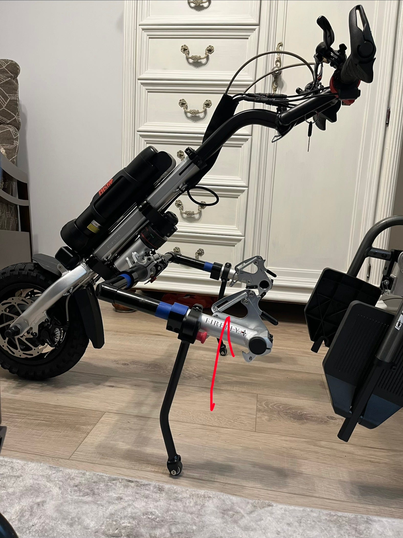
Here is the unit and the Firefly “detached” on its kickstand.
IMHO the Firefly 2.5 is a first class way to power a wheel chair.