Tuesday, June 28, 2022

Weight and Weight/Balance

Weight and Weight/Balance


FAA Part 103 limits the empty weights of an ultralight as 254# or 278# with a parachute. A review of history will provide some insight into how the FAA arrived at these figures. 

The Beginning

Federal Register / Vol. 46. No. 143 / Monday. July 27, 1981 / Proposed Rules

Link to NPRM

Link to excellent commentary

In July of 1981, the FAA's Notice for Proposed Rulemaking regarding ultralights aka powered hang gliders was published in the Federal Register. Due to the growing popularity of hang gliders in the 1970's, the FAA had published Advisory Circular 60-10 in 1974 with recommendations for "safe flying" of hang gliders. Hang Gliding activity continued to grow with flights exceeding 500 feet AGL and with the addition of engines and other control surfaces making some powered "hang gliders" approaching the definition and performance of certificated aircraft. There were a few instances of near miss encounters between ultralights and airliners. It is estimated by 1982, there were more than 10,000 ultralights flying in the US.

Given the FAA's mission to protect the safety of air carrier operations and generally the safety of all airspace users, the FAA determined that additional regulations were needed to define an "ultralight vehicle" and differentiate from regulated "aircraft". The result was Part 103. One major definition of an "ultralight vehicle" is it's weight.

Unpowered "hang gliders" were set at 150#. Powered ultralights without an engine and fuel tank weighed more---in the range of 165-168#.

So where did the 254/278# weights come from?  Federal regulators always seek to find examples of successful real life examples that rationalize the regulations. They found their best example in the most popular ultralight at that time: the Quicksilver MX weighed 254# empty and 278# with a BRS Canister Parachute. 

In some countries, ultralight weight limits are defined by maximum takeoff weight. (e.g. UK max weight limit for unregulated microlight is 300kg=660#  which equates to 380# empty weight carrying 250# pilot and 5 gallons of fuel.) The FAA like some countries (e.g. Germany) chose the vehicle's empty weight. (Germany defined an ultralight as 120kg with a rescue parachute. (264#=14# less than the USA weight)  Using maximum takeoff weight makes more sense if the purpose of limiting weight is to limit performance so as to enhance safety.

The 254# Quicksilver was equipped with a Rotax 447 two cylinder engine. The 447 was heavy as two stroke engines go, as it was equipped with fan cooling and had cast iron cylinder liners. More than 15000 Quicksilver "vehicles" have been sold; by far the most popular ultralight. 

Changes

Rotax stopped production of the 447 model, and Quicksilver adapted a highly modified version of the Hirth F23 engine as it's replacement. The F23 allowed the empty weight to be reduced to 250#. Modifications to the engine are not done in the Hirth factory or by Hirth personnel.

The Aerolite 103, aka the Aerolite 120 in Germany was originally designed in 1996 and first flown in 1997. It was more streamlined than the Quicksilver and weighed slightly more with it's dual surface wings, strut rather than wire bracing, front wind screen and compliant flexible "landing gear".  With less drag, safety was enhanced since there was more time for a pilot to react in an engine out situation. With a flexible suspension, airframe is more resistant to "hidden" damage from hard landings with impacts at 4-5fpm.  The Aerolite 103 with a Rotax 503 engine weighed in at 275#. (Weight of the 503 was about 8# more than the 447. The empty weight without engine of the Quicksilver came in at 165-168#. The Aerolite coming in at 173-178#--i.e. abut 8-10# heavier than a engineless Quicksilver.)

Clearly the Aerolite could not meet Part 103 with the Rotax 2 cylinder engines, so "legal" Aerolites were equipped with one cylinder engines in the US and Germany. (e.g. the Hirth F33)

But, with the introduction of more modern "all aluminum" engines with Nikasil cylinders not requiring fan cooling, being more than 20 pounds lighter than the Rotax engines, the Aerolite 103 could meet the 254# limit with a two cylinder. Just as the F23 Hirth replaced the Rotax in the Quicksilver, the MZ201 engine became a viable engine choice for the Aerolite 103. The MZ201 installed is lighter than the Hirth F23. The F23 has horizontally opposed cylinders requiring two mufflers and two carburetors. The MZ201 has inline cylinders requiring only one carb and one muffler. The Kawasaki 440 is slightly heavier than the MZ201 but enough lighter than the Rotax 447 and the F23 that it does meet the 254# limit using a recoil starter. A flight by 14 year old Scott Henry from Virginia to Oshkosh demonstrated this as shown in the video shared in the above “Transition Training” post.


The greatest advantage of the 2 cylinder engines in ultralight vehicles is the climb rate. The Quicksilver with Rotax 447 and the Hirth F23 advertised a climb rate of 850 fpm. The Aerolite 103/120 with a one cylinder engine advertises a climb rate of only 500 fpm. (Less at altitudes above sea level and/or on a hot day)  With the two cylinder, this jumps to over 900 feet per minute. Higher Rate of Climb is important in regards to safety-- faster takeoffs on grass strips, easier to avoid obstacles, better able to recover from downdrafts or stalls, easier to avoid wake turbulence during takeoffs, and less time running engines at full power. On a hot day, at 1000’ MSL, a single cylinder ultralight might only climb at 5 feet per second and would only clear 80 feet on a 1000 ft runway. A twin engine craft would probably clear the 150 foot obstacle with 1000 foot of runway. Although some 1940 vintage general aviation planes climb about the same as a single cylinder ultralight, the planes generally operate with longer runways. An underpowered ultralight flying off a short private field might attempt to clear an obstacle with too steep a climb and risk an unintended stall.

Weight and Balance


It is important to establish a datum for weight and balance--often it is simple to establish this as a component of the vehicle--in this case, the datum will be the center of the tire. The CG can be established as slight behind the tires (empty) and somewhere forward of the tires with fuel and pilot. The Aerolite 103 will lean back on the tail wheel when empty, but will land as a tricycle gear plane using the front tire for steering when pilot over 100 pounds is on board. Pilots weighing below 150# may require some ballast in nose to insure level flight without excess elevator input. (180-220# pilot weight is ideal). Too light load of fuel and pilot will increase risk of unintended stall and would require excess stick/yoke forward position. Too heavy a load may require excess stick/yoke pull interfering in reaching desired climb. Weight on front tire when craft is loaded and pilot on board should be determined before flight. 

Plane should be able to achieve Vne with power off and stick/yoke forward, and stall speed with stick/yoke at max pull. Level flight with little force on stick/yoke is considered ideal--especially for a plane that does not have adjustable trim.

The following video will show a lifting of a Aerolite 120 with a single cylinder engine with the center of gravity being just slightly to the rear of the tires. 


Here are the actual results of my weighing my Blue and Green Aerolite 103 S/N 210713, nickname “BG” on 8/31/2022 with new Accuteck scale. 119#2oz+119#9oz+11#10oz =250#5oz without wheel pants. Almost exactly as expected from data in literature. CG calculations per manual show CG at 75” from datum (nose) full of fuel with 215# pilot—CG moves rearward 1 inch as fuel is depleted.  

Left Side

Tail (level)

Right Side


Monday, June 27, 2022

Angle of Attack and Stall

Maintaining Control at All TImes

It has been said that the essence of flying an airplane is "Control Yaw and Don't Stall". Another way off saying this is "Control Yaw, Angle of Attack AND Speed" at all times.

Pilots are often taught that air speed determines a stall. This is sometimes true, under certain conditions, however it is NOT true under all conditions. Many a pilot has died trying to pull out of dive by pulling back on the stick too far and essentially stalling the wing, even at very high speed. It is hard to remember to only pull the stick back only enough to arrest the descent while avoiding excess angle of attack as well as avoiding excess g forces.

Loss of control often occurs because a lack of awareness that the use of ailerons will often cause the wing with the down aileron to stall and lose all lift because of the increased angle of attack caused by the change in the airfoil's shape with the down aileron. This is the cause of the infamous stall-spin-invert loss of control during "turn to final". 

Angle of Attack AND Airspeed together creates lift, enabling the plane to fly. Too little angle of attack at a given speed and the plane will descend. Too much and the wing/s will stall, lose lift and descend. The pilot's job is to control lift by adjusting speed and the angle of attack---indirectly with the elevator in the case of a traditional three axis airplane, or more directly by tilting the wing on a trike. 

Other than pointing the plane is the direction you want it to go, controlling yaw has to do with keeping the air flowing over the wing perpendicular to the leading edge and minimizing drag. Uncontrolled yaw will cause increased drag and may result in an unanticipated loss in speed. In addition, the rudder that is used to control yaw, also causes one wing to rise and the other to fall.

But Angle of Attack works together with Speed, so uncontrolled Yaw and increased drag, reduces speed and therefore reduces lift.  And adverse yaw (in the opposite direction of travel) creates and need to increase aileron input, increasing the angle of attack on the high wing. 

I fine point often misunderstood, if the concept of "relative wind" over the wing. To illustrate, let's use an example. Assume the plane is flying at 50 mph and the pilot reduces speed by reducing power, and maintains the same nose up/down attitude using elevator--the plane will descend without changing nose up/down attitude--the angle of attack seen by the wing by the relative wind will increase. A high drag ultralight will slow rapidly and in order to avoid too rapid a descent, the pilot may be tempted to pull the stick back---resulting in an further increase in angle of attack to the point of stall. To avoid this, unstable scenario, the descent in an ultralight should always be with sufficient nose down elevator to maintain a safe "margin" of "reserve angle of attack". 

Ultralights are often capable of very steep climb attitudes. When climbing the relative wind tends to decrease the angle of attack. This can create a dangerous situation: 1) With a sudden loss of power; or 2) With a sudden change in wind conditions---as angle of attack could increase suddenly causing a stall. 

Bottom Line---Determine the "safe" nose up attitude for climbs and nose down for descents, devise a way of determining these attitudes and use this to maintain a "reserve angle of attack" for descent, level flight and climb. 

Keep in mind that most planes have a "built in" angle of attack to allow "level" attitude at cruising speed. An increase in power and a change to a nose up attitude will cause the plane to climb. A decrease in power and a change to a nose down attitude will cause the plane to descend. Remember BOTH air speed and nose attitude will determine angle of attack.


Angle of Incidence + Pitch  =
Angle of Climb + Angle of Attack

For example if Angle of Climb is held constant, a change in pitch equals (created by stick back and reduction in throttle) an exactly equal change in Angle of Attack. 

Another example (with negative pitch and negative climb) If Angle of Climb reduced to descend, then Angle of Pitch must be reduced by same amount with stick forward in order to keep Angle of Attack unchanged. Without moving stick forward to reduce Angle of Pitch, Angle of Attack would increase.


To make planes "safer", most general aviation planes incorporate a feature called "Wing Washout" where the wings have a higher angle of attack (2-3 degrees) near the root than at the tips. This causes the wings to stall "smoothly" with the wing first stalling at the root, allowing the ailerons to still be effective.  


Most ultralights (including the Aerolite 103) do not have any washout. Hence, the stall will occur more suddenly across the entire wing simultaneously, with less "warning" and with the high probability that one wing will drop, with the plane entering a down spiral or spin--especially if the plane's rudder is not perfectly centered.  Hence managing angle of attack and maintaining a "reserve angle of attack" on an ultralight is very important.

Here are two ways to measure AOA without fancy electronics:


The Wright Brothers used a similar method on their first flights.


The Concept of TOP RUDDER 

Whenever an ultralight encounters a situation where a stall does occur and the plane enters an down spiral or spin--remember that abrupt input of top or opposite rudder is the only input that will allow the pilot to regain control. Generally, the best position for the ailerons during this "recovery" is neutral, and of course whenever there is a stall, the stick should be moved forward to increase speed and airflow over the wing.  The use of ailerons when stalled or in slow nose up high angle of attack flight can be ineffective and/or dangerous as they change the angle of attack on each wing differently.


Sunday, June 26, 2022

Fuel and Oil for the MZ201 Engine

Fuel and Oil for the MZ201 Engine

Fuel and lubricating oil are important for any engine. For a 2 stroke engine, where the engine is lubricated with a fuel/oil mixture fuel and oil are especially important. And, while fuel and oil are important for 2 stroke outboards, motorbikes and snowmobiles, they are critical for an ultralight.

Engine out failures in an ultralight most often result in emergency landings, so the importance of avoiding engine failures is obvious. 

The most common engine out failures in two stroke engines are the result of detonation, excess deposits of carbon from unburned oil, seizures due to a lack of sufficient lubrication, or dirty contaminated fuel. 

Fuel

Detonation or "ping" is caused by fuel that burns as an explosion rather than a relatively more controlled more gradual pressure increase over time. It is like hitting the piston with a hammer rather an a push. For the sake of simplicity, assuming ignition timing is set correctly, detonation is the result of fuel with insufficient octane rating, excess carbon deposits in the combustion chamber or incorrect air fuel ratio. 

The correct air fuel ratio is usually just a matter of adjusting and/or jetting the carburetor correctly for air density and humidity.

So picking the right fuel becomes a bit of a research project. And, it must be remembered that adding oil to the fuel tends to reduce the octane rating.

Compact Radial Engines and now Fiate, manufacturer of the MZ201 recommend minimum 95 RON Octane gasoline. The engine is advertised to have a 9.6:1 Compression Ratio.

Gasoline sold at automobile service stations generally only share the AKI rating of the fuel. AKI is an average of RON and MON. Generally RON is higher than MON and AKI for the same fuel. e.g. 93 AKI "Supreme" gasoline at most service stations is equal to 98 RON, but it achieves with 10% ethanol. Most ethanol free gasoline at the service station pumps is 90 AKI, with an estimated 91 RON. Since 91 RON is too low and ethanol is not recommended for "aircraft", the only way to use "pump" fuel would be to blend it with Aviation Gasoline 100LL or an unleaded "racing-off road" gasoline. 

100LL Aviation Gasoline has a MON of 100, with an estimated RON of more than 105 (As high as 110). A 50% blend of 90 AKI ethanol free pump gas and 100LL would result in a fuel that exceeds the minimum 95 RON requirement with an estimated RON of 98+. Sunoco 260GTX 98 AKI Racing Fuel has a RON of 103. A blend of 40% pump and 60% Sunoco GTX  would provide an RON of 98 and it would be unleaded.  (Too high an octane is not ideal as higher octane tends to burn more slowly, so there could be incomplete combustion and less power.)  


Another option is Sunoco Optima 95 (what NASCAR Cup uses) which is unleaded and has an RON of 98. The advantage of the blends is that pump gas and Optima have a relatively high vapor pressure compared to 260GTX and 100LL.  As of July 2022: Cost of the 100LL blend would be around $8 per gallon. Cost of the Sunoco blend would be around $12. Cost of the Optima or unblended 260GTX would be $18-20 per gallon including shipping costs. 

It is possible that the MZ201 engine could run better with 103 RON vs 98, depending on ignition timing, so the Sunoco 260GTX might be ideal under certain circumstances. Detonation in an ultralight engine will likely not be detected by an audible "ping" like in an automobile. Signs of detonation will show up in the form of excessive CHT and depressed EGT with some loss of power. When octane is too high or the timing is not advanced enough, the engine will produce less power and will show a lower CHT. All of this complicated by the fact that flame speed is also affected by the fuel air ratio--too lean a mixture can produce the same effect as low octane. Slightly "rich" of peak is usually best. 


Sunoco offers Optima 95 "pre-mixed" with a synthetic 2 stroke oil with a 40:1 ratio. The 2 stroke oil meets JASO FD and API TC Specs. Sunoco does not provide any other tech data on the oil. Since it is advertised as recommended for outboards, it might not be ideal for air cooled engines.

My best judgment will be to run Sunoco 260GTX and experiment with blending it with 90AKI ethanol free pump gas when ambient temps are lower. If 260GTX became unavailable, I would use 100LL blended with 90AKI. While 260GTX is more expensive, the convenience of buying in 5 gal pails, and the logistics of obtaining/transporting 100LL offset the cost.

Oil

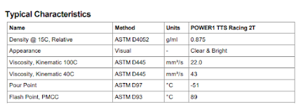
The MZ201 Engine Manual specifies Castrol TTS as the desired oil, mixed at 50:1.  Castrol TTS is no longer produced, so something else must be identified.

First let's look at the specs for Castrol TTS (as of 2016):

  • Full synthetic 2-stroke motorcycle engine oil
  • Creates a tough, heat-reactive layer of protection
  • Designed for both oil injection and premix lubrication up to a fuel/oil ratio of 50:1
  • Exceeds API TC, JASO FD, and ISO L EGD

API is the American Petroleum Institute, and TC is a very old standard met by almost every 2 cycle oil sold today.

JASO FD is a Japanese more stringent standard requiring lower smoke levels and more detergent.

ISO L EGD, a European standard is essentially the same as JASO FD, but requires a  3 hour test running a Honda engine to document piston cleanliness and detergent effectiveness.

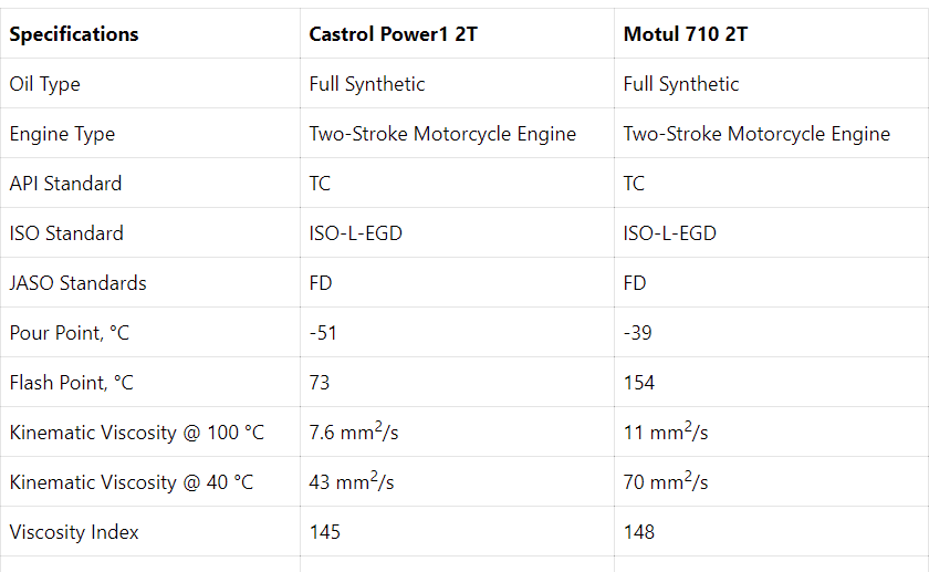
Castrol has introduced "replacements" for TTS,  Castrol Power 1 2T.  Amsoil Dominator is almost the same. Motul produces a similar product, Motul 710 2T. 


Castrol Power 1 2T seems to be in very short supply in the US. Motul 710 is available from multiple sources. The Flash Point of 154C for the Motul is more desirable than the Power 1 2T and Amsoil as is the higher viscosity.  The viscosity of Motul 710 is higher than Power 1, but lower at 100C than Castrol TTS. My opinion is that Motul 710 2T is equivalent and slightly better than the Castrol TTS.  

Another "equivalent" oil would be from Motorex (Switzerland)  Cross Power 2T.  Flashpoint is 110C with Kinematic Viscosity at 40C of 60. This is in between Castrol and Motul 710.

Motorex Power Synt 2T is advertised as designed for “Supersport” motorcycle racing. Similar specs as Cross Power 2T.

Another "possible" oil would be Motul 800 Off Road 2T with Flashpoint of 252C, and Kinematic Viscosities of 120 and 15.

                                                    Flash Point C  Viscosity@40C Viscosity@100C

Castrol TTS                                    89                    43                     22  

Castrol Power 1 2T                        73                  43                      8

Amsoil Dominator                           94                   35                      7

Motorex Cross Power 2T               110                   60                    NA

Motorex Power Synt 2T                  108                50                    9.1

Motul 710 2T                                  154                   70                    11

Maxima 927                                    218                                                                                   155.                 15

Motul 800 OR 2T                            252                   120                  15

Note: Castrol (UK)  Motul (France), Motorex (Switzerland) all comply with JASO FD and ISO L-EGD as well as API TC.  Maxima and Amsoil, both USA companies did not go to expense of testing to meet other than API TC.

The Maxima 927 oil has been around a long time—since the 1970’s and was formulated for racing. Lower viscosity oils were developed to enable flow thru oil injector pumps rather than pre-mix. Maxima 927, like Motul 800 with higher viscosity and flashpoint was for pre-mix only. Maxima 927 is a blend of castor oil and synthetic. Castor oil can provide superior lubricity, but tends to create deposits when run at less than maximum output. Maxima claims to have solved this problem with blending. Pre-mix ratios are changed based on the type of use.

Motul 800 is designed for all out motorcycle racing, lots of full throttle, very high RPM operation. The others are designed for less severe use, less full throttle and lower RPM and are also suitable for chain saws, with intermittent full throttle. Air cooled motorcycle engines and chain saws operate under different conditions than an engine driving a propeller in an aircraft. 

The ultralight aircraft is likely to see full throttle for for one to two minutes during takeoff and climb, and then would be at a lower RPM for cruise. Load for propeller equipped engines is more or less correlated to RPM. (Actually load increases at a faster rate than RPM, but for the range considered, assume it to be linear.)


There is no two stroke engine oil that is expressly designed for ultralights. (Blue Max is one exception that was marketed by the former importer of Hirth engines--but there were no specs provided for that oil--only marketing claims and the fact that it was not a synthetic oil.) In fact, Amsoil will not sell their oil for any "aircraft" application, and all oil manufacturers will be quick to assert that they do not recommend their oils for aircraft operations since they have never been tested for that application. (Amsoil and others probably just wanting to avoid legal suits but demands for oil in ultralights IS different from other applications.)

During that two minutes of climb (red), clearly Motul 800 with a high flash point and density would be a very good oil. But, during cruise (green) it might not vaporize and burn sufficiently to avoid smoke, oil in the muffler, and carbon deposits on the piston. And , during descent (yellow) it would not vaporize and burn sufficiently to avoid smoke, oil in muffler and carbon deposits. 

Most likely the Motul 710 2T would be ideal for both cruise and descent. Feedback from users indicate that 710 is great for "normal" motorcycle operation, with 800 producing a lot of oil in the muffler, called "spooge". 


The fuel/air/oil mixture flows into the crankcase. Being relatively "cool" the mixture directly cools and lubes the crankshaft and conn rod bearing which probably run at a temp below 150C. The mixture also impacts the lower cylinder, probably running at a slightly higher temp. In addition, the mixture also impacts the piston pin and bearing, cooling and lubing it. However, the piston is much hotter, probably running hotter than 150C. Here, a higher flash point can be attractive.

This all focuses on the oil's flash point and to a lesser extent, viscosity. Does the oil vaporize completely during this charging and transfer phase? How much, if any, is the lubrication of the piston pin and bearing affected if the temp is higher than the flashpoint? How much oil remains on cylinder walls?

Reviewing the specs for Castrol TTS, with a flashpoint of only 89C, and MZ201's manufacturer's recommendation, it would appear that a low flashpoint is not too much of an issue. This is confirmed by Aerolite 103 factory and US distributor for the MZ201 who claims Amsoil Dominator at 50:1 is being used with no problems, Motul 710 2T has a significantly higher flashpoint at 154C than Castrol TTS's 89C. And, Motorex’s Supersport racing oil has lower flash point and viscosity than Motul 710. (KTM exclusively uses Motorex, so they raced at “supersport” level with oil with less than 150C flash point, so perhaps higher flashpoint is not necessary. Motorex does recommend 40:1 for supersport racing.

Other than the mess of oil dripping from the muffler onto the ultralight's wings and tail, the another concern about using Motul 800 would be deposits---especially deposits that cause piston ring sticking and damage. Anecdotal evidence does not point toward carbon deposits with Motul 800, perhaps due to detergent efficiency.  And anecdotal evidence with small high RPM motocross racing engines running Motorex (similar to Motul 710) shows more than sufficient lubrication after disassembly and inspection at 50 hours. 

One possible "solution" would be to blend 710 and 800 together to raise the flash point and viscosity. Another would be to increase the ratio for 710 from 50:1 to 40:1 or even 30;1 while insuring a slightly rich above peak air fuel ratio, Another would be to use Motul 800 or Maxima 927 when ambient and cylinder head temps are high, living with the spooge generated during descent. 

It is generally accepted that higher rpm requires a pre mix with more oil, e.g. 40:1 vs 50:1. It must be remembered that the MZ201 is running at half the rpm of racing motorcycles and less than 1/3 the rpm of racing karts.

It appears that whatever oil is chosen, due to the unique loads imposed on ultralight engines, optimum oil and ratio will result in some sponge at low loads encountered during descent. This provides an insight that best operation is to minimize idle and low rpm, using some throttle and higher rpm with lower descent rates during landing pattern. It also indicates that oil with more “solvent” which is used to reduce lower temp viscosity and flash point may be desirable in minimizing carbon deposits. The viscosity of the various oils at 200C “where it matters” are much more comparable than the 100C figures would indicate.

Motul recommendations:

Motul 710--Mixing ratio: from 2% to 4% (from 50:1 to 25:1) according to manufacturers' requirements. Adjust according to your own use.

Motul 800 Mixing ratio: MOTO CROSS GRAND PRIX: 2% (50:1). In normal conditions decrease the percentage by 0.5%. (66:1) Tune according to your own use.

Engine size does affect the decision regarding the "best" oil and mixture. A one cylinder MZ engine will run at 50% higher RPM and likely to be run at maximum load for much longer to climb than a two cylinder MZ201. Another factor to consider is the effect of prop pitch on engine load. With an adjustable pitch prop, one can choose a setting that creates a higher climb rate, reducing the time at full throttle during take off and climb but requiring a higher RPM for cruise. If one planned on long cross country running, choosing a setting for low RPM at cruise would be ideal, overcoming the reduced climb rate by climbing in stages, limiting full throttle to 30-60 seconds at a time. 

Also important to note is that changing oils and ratios probably will require an adjustment to the air/fuel ratio. Oil has as at least 10 times the viscosity of gasoline and higher viscosity oil will orequire larger (more rich) jetting. (The same vacuum pulling the thicker mixture will produce less flow.) Increasing the oil ratio from 50:1 to 40:1 will also reduce the combustible fuel thru the jetting, requiring more rich settings. In my opinion, an oil with a relatively lower viscosity, if sufficient to support oil film loads, will perform better than a relatively thick oil.

Based on the fact that Motul 710 2T is similar to Castrol TTS and Motorex, but with slightly higher flashpoint, and Motorex recommendation of 40:1 for racing, my best judgment indicates I will run Motul 710 2T at 40:1 (3.2 oz per gal = 2.5%)  in my MZ201, being careful to control (limit) full throttle for extended periods of more than 60 seconds, and limiting off throttle idling on the ground and during descent. I will also run air fuel slightly on the rich side and will monitor CHT closely.

Absent testing, followed by disassembly and inspection, choosing the ideal oil and mixture is not possible. One can only choose a "conservative" strategy with the highest estimate of a good outcome, but having a "safety" factor. And, during operation, make close observations as to smoke, spooge, and CHT. One of the fundamental aspects of “unregulated” flight is personal responsibility—no FAA Reg’s certifying what products and procedures to use..you are responsible for determining what is best.

Additional Note:  An often unrecognized characteristic of 2 stroke cycle engines, particularly those that are not fan cooled is the effect on air fuel mixture by crankcase temperatures. The crankcase temp of so called “air cooled” engines varies tremendously and hence the mixture can become dangerously lean when ambient temps are low. This is particularly critical during descent when power output is low and is made worse with fuels having low vapor pressure. 

In addition, the volume to area ratio is also critical. A crankcase with a relatively large surface area relative to its volume is more likely to create lean air fuel ratios at low ambient temps. The MZ201 was designed originally as a two carburetor fan cooled engine. Reducing air flow with only one carburetor and eliminating the fan makes the engine particularly at risk for the dangers of lean air fuel rations—and potentially a complete engine shutdown when applying full throttle after a period of descent. This is the cause of my crash. 

Saturday, June 25, 2022

The Tillotson HR197A Carburetor-Air Fuel Mixture Setting

 The Tillotson HR197A Carburetor Air Fuel Mixture Setting CHT and EGT

In the previous post, it was noted that air fuel ratio needed to be adjusted. In most general aviation planes, the air fuel ratio is cockpit adjustable. The MZ201 engine, equipped with the Tillotson HR197A carburetor does not offer this feature without modifications.


Jack B. Hart's blog provides an excellent illustration of the HR197A. He did make such modification as seen in this link:

Carb Mods

The Tillotson carb has two "mixture" adjustments: Low Speed and High Speed. The Tillotson Manual suggests starting out with "one full turn out" on both. Other anecdotal suggestions from users of the carb on vintage snowmobiles is 3/4 turn out on Low Speed and 1 1/4 turn out on high speed. 

Setting the Low Speed is more or less the same process for setting idle mixture. Turn out--to richen until it stumbles and turn in slightly to smooth it out. 

Setting the High Speed is more complicated as it requires the engine to be run at full speed wide open throttle. One can restrain the ultralight and run on the ground for short periods, but with the lack of air flow from actual flight, there is a risk of overheating. 

Perhaps the most accurate way to determine the ideal setting is the use of the Tillotson Quick Jet tool. (See below) It allows precise and repeatable settings.

Each mark on dial is 1/30th revolution


Take careful notes


During flight, High Speed mixture exists while the plane is in a full power climb for 30 seconds; the CHT and EGT and EGT should be noted. The "ideal" setting would be to find the setting that produces what is generally referred to as 100-150 degrees ROP. (ROP=Rich of Peak EGT). This ROP setting procedure is similar to the system used for GA planes with cockpit adjustable mixture controls.

Four stroke engines can use a air fuel gauge that measures oxygen in the exhaust, but these systems do not work as well in a 2 stroke because of the oil mixed in with the fuel. 

Cylinder Head Temp or CHT should be kept below 380 F. (Fiate suggests a max of 500 F, but engine life at temps above 400 F is seriously reduced.) Anything that makes the air fuel mixture burn faster increases CHT. The fastest burn rate occurs with an air fuel mixture slightly more rich than 14.7 pounds of air per pound of fuel=approximately 50F ROP EGT. Leaner mixtures will have lower CHT and richer mixtures will have lower CHT.

Peak EGT will be at the 14.7:1 ratio referred to as "Stoichiometric". This would be ZERO ROP. Increasing the fuel (turning the High Speed adjuster out) will decrease EGT. Assuming the adjustment is reasonably "close" because the engine is running smoothly, if an increase in fuel causes a increase in EGT, you are on the lean side of peak. If an increase in fuel causes a drop in EGT, you are on the rich side of ZERO ROP. 

Once peak EGT is identified, increasing fuel to richen the mixture will reduce EGT. The ideal would be to be in the 100-150 F ROP or 100-150F below peak EGT. (100 ROP is theoretically maximum power; 150 ROP has a slightly lower CHT for maximum engine life--remembering that 2 stroke engines are cooled by fuel.) Keep in mind that these readings assume you are at maximum power and wide open throttle in climb (46 mph for the Aerolite 103) for long enough time to allow the CHT and EGT to "stabilize".  Having that cockpit adjustment mod like Jack B. Hart's would make this an easy process--without it, would require several repeated flights. 

Prior to actual flight, lean the high speed jet from the "initial reference" setting by one or two 30th marks on the Quick Jet tool and continue if EGT at full throttle run up increases--stop when it approaches max 1250F. (You will also note some "dull" acceleration during a takeoff roll at around 4000-4500 RPM.) Then richen the mixture five (5) 30th marks. Lean the low speed jet until the engine idle speed (set at 1650 rpm) drops, then back one 30th mark. Test the engine during take off roll to verify no "four stroking" in the 3000-4500 RPM range and no "dull" acceleration above 4500 RPM.

Note: Excessively rich LS jet will cause "four stroking" and even engine out during acceleration as engine travels past 3000-3500 RPM---this is because the LS jet has an idle port and an "intermediate" or secondary port that adds considerable fuel in this RPM range during which the HS jet is also "kicking in".  The danger from high EGT will occur during high rpm and high loads, and the engine is likely to have "dull" acceleration if too lean, hence the HS jet should be on the rich side. On the other hand, the LS jet should probably be set as lean as possible to avoid "four stroking" during take off roll. 

This "ideal" performance (prior to first flight during take off roll tests) occurred with settings of 1+6/30 on the HS and 1+3/30 on the LS with Density Altitude of 1200 feet. Best estimate is that engine is set at 150 ROP estimating that each 30th moved EGT down by about 25-30 degrees. (Re-adjustment may be required if Density Altitude changes substantially. ) A final check would be to look at plug condition after a take off roll. (Look for a light tan insulator and a dry electrode.)

Note that all of these adjustments depend on a propeller pitch setting that "governs" RPM during takeoff roll in the 4800-5200 RPM range. If the engine spins above that under load during take off roll, the engine RPM is being limited by the carburetor's maximum air flow and all mixture adjustments will be incorrect (probably too rich) due to excess turbulence in the carb's venturi.


Too much white on insulator is bad-too lean


Medium Setting for 1000-1500 Ft Density Alt


Rich Setting for <500 Ft Density Altitude 


Medium Setting "some four stroking" at 1500 DA; Rich Setting "some four stroking" at 500 DA. Appears 1/30 change is appropriate for High Speed Jet for 1000 Ft change in DA. Since EGT in 4500-4700 RPM "cruise" shows 1225+ EGT with the lower DA "Rich" setting, it may be prudent to run a bit on rich side.

Here is a link to articles about adjusting the mixture.

http://www.iwt.com.au/tillotson.htm

https://resources.savvyaviation.com/understanding-cht-and-egt-2/

In general aviation, running LOP increases fuel economy and mixture must be generally leaned at higher altitudes. Ultralights are generally not flying high enough to require in flight adjustment. Choosing maximum engine life over best fuel economy is a matter of pilot choice. To minimize risk associated with engine outs in an ultralight, I would always choose to maximize engine life. 

The Aerolite 103 nicknamed "BG" for its blue and green colors will be equipped with the Grand Rapids EIS showing CHT and EGT. 


Wednesday, June 22, 2022

Carb Ice--Ultralights

Carb Ice-Ultralights

Any engine equipped with a carburetor is subject to carburetor icing. One purpose of the carburetor is to control the flow of air and fuel.  The other is to cause the atomization of the fuel and to mix it with the air.  The means used to move the fuel into the air is a pressure difference between the fuel supply and the air--this pressure difference is caused: 1) thru the use of a venturi that increases velocity, thereby reducing pressure; and 2) by the restriction caused by the throttle plate or slide. Fuel enters the air thru an orifice (i.e. "jet") that begins the atomization process which is then further developed as the fuel is broken into small droplets by the moving air. The amount of fuel is more or less "controlled" by change in air flow with change in throttle position somewhere in the range of 13-15 parts air to 1 part fuel.

When air is accelerated thru a venturi, the pressure is reduced as is it's temperature. When pressure is reduced by the restriction of the throttle plate, temperature is reduced. Hence air flowing thru the venturi that impacts the downstream throttle plate is colder than ambient and air downstream of the closed or partially closed throttle plate is even colder. 

While the air actually cools the atomized fuel, the relatively volatile gasoline will still begin to evaporate. Gasoline is a mixture of many different fluids that evaporate at different temps. Some of the compounds will evaporate at temps as low as 40F below zero. The evaporation of the more volatile gasoline components will cool the air and surfaces of the carburetor significantly. 

The amount of moisture in the incoming air will determine what happens when the air and carburetor surfaces are cooled. If the air is cooled below the "dew point" then water vapor will condense to liquid and wet the inside of the carb. If the surface/s of the carb are below freezing, then ice will form. IT IS THIS LIQUID WATER IMPINGING ON A CARBURETOR SURFACE THAT IS BELOW 32F THAT FORMS THE CARB ICE. 

So, first there must be enough water vapor in the air that a reduction in air temperature causes the water to condense. Second, the surface/s of the carb must be below 32F.


The chart above shows the various temperature and humidity levels and the corresponding risks of carb ice.  Note that carb ice is always more of an issue during "glide" with a closed or partially closed throttle. 


Note that the difference in the amount of air flowing thru the carburetor from 40% throttle to full throttle is only 10-15% but falls off below 40% throttle. Ice forming below 40% throttle is therefore much more due to fuel vaporization than due to reduced pressure and velocity in the venturi. The reduced pressure causes a higher rate of evaporation and more temperature drop than any temp drop due to the reduced air pressure itself.  A large part of the fuel in this "intermediate" and/or "idle" stage is from the low speed jet downstream from the throttle plate. 

The above assumes a careful pilot that avoids flying in clouds and conditions of very high humidity. 

The Tillotson HR197a Diaphragm Carburetor shown below and used on the MZ201 is a bit different than the Bing 54 Carburetor variable sliding venturi on a Rotax or other “slide” carbs like Mikuni’s on Kawasaki 440. The Bing and most “slide types” are much less susceptible to carb ice. On the Tillotson, carb ice is likely to occur downstream of the throttle plate butterfly. But, any carb where fuel is evaporated and not just atomized inside the carb is susceptible to carb ice under certain conditions.

(Butterfly throttle plate carburetors have different performance characteristics as compared to slide type carburetors. The butterfly types are thought to have better performance during the transition from 60% to full throttle. The butterfly throttle plate is less ideal with less than 50% throttle.)


To offset the heat lost from the carb surface and air to the evaporated fuel in order to raise the carb temperature there are five sources of heat input to prevent or melt ice:  1) Heat from an external source heating the air or the carb itself: 2) Heat added from air flow on the outside surfaces of the carb assuming ambient temps are above 32F; 3) Additional ambient temp air into the carb caused by opening the throttle assuming ambient temps are above 32F; 4) Heat conducted from the engine to the carb via the manifold; 5) Heat radiated from the nearby cylinder head cooling fins.

So, assuming ambient temps are warmer than 32F, increasing the load and RPM by opening the throttle will add heat and increase the carb temperature. Granted more fuel will be added, but the increased air flow at 13-15:1 ratio will overcome the heat lost due to evaporation. 

Remember, during conditions when carb ice is probable, carb temps will almost always be lower than ambient temps which often results in condensation inside and outside of the carburetor. Ice can only form on the inside of the carb if it’s inside surface is below 32F,

The existence of carb ice is difficult to “prove” or document as the “evidence” tends to disappear by melting before the carb can be expected. There are many anecdotal “stories” of “near death experiences” and engine out accidents blamed on carb ice.  Some of these issues may have different causes such as contaminated fuel. But no doubt, carb ice can form and can block the low and intermediate jets causing engine shutdown with a restart being impossible while in flight. 

It is also possible when ambient temps are low, in high humidity for ice on the outside of the carb without internal carb ice being present. 

Most General Aviation planes with air cooled engines have a ductwork system that provides air heated by the exhaust pipes directed into the carburetor, controlled with a “carb heat” control cable. This is impractical for ultralights because of weight. Motorcycles and snowmobiles sometimes have an electric heating element attached to the carburetor body. This is possible and an elegant solution but again can be impractical due to the weight of the necessary large capacity battery.

The photo below from Jack B Hart shows a HR197a Tillotson Carb with a heating element installed. Jack does not share whether it was effective.


One necessary item that needs to be added to an ultralight is a carb temp gauge. I believe the GRT EIS had an option for this readout. The sensor that can be used is similar to those used for CHT. The carb temp gauge will alert the pilot to a cold carburetor where carb ice might form. Testing will determine the correlation of the carb temp gauge reading to the actual surface of the inside throttle bore just downstream of the throttle plate. In other words, a reading of 36F on the gauge may indicate 32F inside the carb.

I conducted a diligent research effort to find any scientific or technical research on the effect of using a typical two stroke cycle fuel/oil mix. I found none. But here is my hypothesis: THE OIL MIXED WITH THE FUEL SIGNIFICANTLY REDUCES THE AMOUNT OF FUEL EVAPORATION INSIDE THE CARB. FUEL EVAPORATION OCCURS DOWNSTREAM OF THE CARB INSIDE THE CRANKCASE WHERE THE MIXTURE IMPINGES ON THE CRANK AND ROD, AND IS VIOLENTLY AGITATED BY THE ROTATING PARTS BEFORE ENTERING THE CYLINDER.  IN ADDITION, THE OIL CREATES A FILM ON THE CARB SURFACES MAKING THEM LESS SUSCEPTIBLE TO ICE ACCUMULATION. HENCE, TWO STROKE ENGINES ARE LESS SUSCEPTIBLE THAN FOUR STROKES TO CARB ICE. 

Carb ice can form in a two stroke engine—ice will simply form more often and more easily in a four stroke. A four stroke needs a more aggressive system to prevent and overcome carb ice.

To prevent carb ice with a two stroke engine ultralight (particularly for engines having carb with throttle plate vs a slide):

1) Avoid flying when ambient temps are in the 30-65F range when the dew point is less than 15F lower than ambient. Keep in mind that temps and humidity are often different at higher altitudes. (Avoid the red zone in the chart) Avoid flying near clouds or in hazy high humidity inversion layers or areas with light ground fog. (Generally afternoon flying is safer than morning flights as the “dew point spread” generally is higher in the afternoon.) This “rule” applies to all engines-even those with slide controlled carbs like the Bing 54.

2) Avoid prolonged periods of operation with less than 50% throttle. Pressure downstream of the throttle is significantly lower with much higher fuel evaporation cooling at low throttle positions. Periodically apply full power to maintain CHT. Avoid sudden reduction in throttle. (Prop pitch is part of the equation—cruise level flight should only be possible with more than 50% throttle and ultralight should descend with 50% throttle. My preference for an ultralight is more a “climb” than a “cruise” prop. This limits top speed, but provides other benefits including faster climbs, less engine stress, and shorter takeoff rolls,

3) During “glide descent” for landings use forward slip to steepen descent so as to avoid prolonged periods with less than 50% throttle. Periodically apply full power to “clear” engine and maintain CHT.  Do not reduce power below 50% until you are sure you can safely land with a possible hypothetical engine out, prop stopped scenario.

4) Diligently monitor Carb Temp and EGT. Ice formation is often indicated by a drop in RPM and EGT.

To deal with impending ice or to melt ice formed: Raise carb temp by increasing load and RPM. In other words, full power and climb at Vx=40mph. This introduces a massive amount of warmer ambient air (if above 32F) and increases cylinder and engine temp. Move throttle to break any ice formed. Remember that the ice, if any is interfering with the low and intermediate fuel jets but not the high speed jet. Identify an emergency landing site just in case. Do not reduce throttle until a “safe” carb temp is reached, signs of ice are eliminated, and an emergency landing site is identified.  Return of the throttle to 50% throttle may cause an engine out if ice is still present.

Another consideration is to use fuel with a relatively lower initial volatility. In other words a low Reid Vapor Pressure and a relatively high 10% Evaporation Temp. Combine this with a 40:1 fuel oil mixture ratio and temperature drop in carb will be reduced significantly from pump gas and 50:1 mix. 

Fuel                             Reid VP   10% Evap

Sunoco 260 GTX         4.7            182 F

Sunoco Optima            7.0            140F

Pump Gas                   9-15           100-120F


Note: Remember that the formation of ice in the carb generally requires the water vapor to change to a liquid. In other words, the temperature of the air needs to fall below the dew point. When the dew point is below 20F, generally the vapor will change quickly to ice crystals and flow thru the carb with little adverse effect.


Tuesday, June 21, 2022

On Board Communications

On Board Communications

There are no regulations requiring a radio while flying an ultralight. It is prudent however to use a radio while taking off and landing from public airfields. It would be necessary to have a radio in order to ask for "permission" to land at an airport in "controlled" airspace--most likely at a Class D airfield. 

The weight of a hand held aircraft spectrum VHF radio is minimal and even with it's low 5 watts of power, it is adequate for the needs of an ultralight pilot. Here is a picture of the ICOM A24 I use. Actually, the transmit power for voice is much lower than 5 watts.


The next issue is the decision of the pilot "interface".  One common interface is a standard pilot's headset.  (I have a simple David Clark "mono-passive" one)  These require the use of ICOM's adaptor and an additional "PTT=Push to Talk button. Note the two pin connector for the radio and the dual GA plugs 0.25/0.206 dia. The small plug is for the PTT harness.


The traditional aviation headset requires a special type of helmet with clearance for the ear muffs. Another option is to use a full face motorcycle helmet with speakers and mic installed.


I prefer the full face helmet when flying in an open cockpit like an ultralight. It protects the face in an impact (accident or bird strike) and also better protects the nose and mouth from insects. In addition, the output impedance of the ICOM A24 is 8 Ohms vs general aviation’s 130. So the David Clark headset would have limited volume to the ears. 

I attempted to use the Midland radio "kit", but the two pin plug is wired differently and not compatible with the ICOM. I attempted to rewire it, but the 28Ga wires were so small and fragile, I abandoned the effort and will go with a "NASCAR" stereo single 1/4" jack (RJS 600080174) setup with an adaptor to the dual GA jacks. 


The "NASCAR" setup from RJS needs an adaptor cable to go from single 1/4" jack to the dual GA setup as mentioned. I ordered the one that converts the "ultralight" single jack to dual GA. The "ultralight" wiring is used by Comtronics in their headsets. The setup did not work! Lot's of research and I found a wiring diagram for the "NASCAR" wiring. 


Seems that the "NASCAR" wiring uses the center "band" for the speaker and the tip for the mic.  I figured this was opposite from aviation, so I disassembled the adaptor cable and re-soldered the wires reversing the green and the red wires, essentially making the center band of the NASCAR jack connect to the tip of the aviation wiring jack/plug.  It worked!  I tested the mic by increasing the side tone and speaking into the mic to hear myself on the speakers. I will install in my full face helmet. I will need a 1/4" extension, female on one end and male on the other to run from my helmet to the adaptor cable and radio. I may be able to reach the transmit button on the radio, but if not, I will add a PTT switch that plugs into the ICOM adaptor wiring.

In addition to radio communication with controllers and other aircraft, I found it potentially useful to also enable cell phone communication. Bluetooth technology and voice control makes this feasible.  I tested these over the neck J-Lab earphones that see to fill the bill. They have Active Noise Reduction.  I can actually wear them inside the speaker equipped helmet and/or the David Clark headset. 


Finally, another option for the radio use is to go with a handheld "speaker-microphone" used by police officers. Radio use is in an ultralight is usually much more limited than for general aviation. For years (headsets did not become popular for general aviation until the 1980's--I learned to fly in the 1970's using hand held mic and a panel mounted speaker in the cockpit.) pilots used a handheld mic for communication, And, even when wearing a helmet, the speaker is probably loud enough with proper placement in/next to the helmet. One issue is that you would probably not hear the speaker when "stowed" i.e. when not holding it, so it would be only useful when you intended to listen and talk rather than listen only. Could be an advantage in that you would not be distracted by non-applicable radio "traffic". We will see.


In flight testing will determine how these systems work while flying an Aerolite 103.

A third option is to use wireless Bluetooth technology from Sena. 

SR10-10 


SMH 10-11


Smart Helmet and Speakers/Mic from Sena


Navigation

Ultralights are required to obey FAA Regulations. One of the most important is the limits on airspace that require reasonably precise navigation. 

This can be achieved by using regular on line maps, including Google Maps with GPS and free VFR Sectionals at http://vfrmap.com or SkyVector.com/. SkyVector and vfrmap.com and Google Maps would only be available when connected to the internet via cellular or wifi,  In flight can be achieved without a cellular data plane by subscribing to ForeFlight or free apps AVARE for Android or FltPlan Go for Android or Apple. The free apps are a bit less capable in terms of all forms of flight info, but are very good for GPS navigation for any device where sectionals can be downloaded and stored. 

I carry a leg mounted device that holds an IPAD Mini equipped with GPS and FltPlan Go for this purpose. I carry an iPhone and I also have an android phone with Avare available. The phone's display is really too hard to read when flying. The leg mounted IPAD Mini works very well. 


Google Maps Satellite view provides another useful feature when flying an ultralight. You can identify clear farm fields along a route to insure you abide by regulations for avoiding populated areas and always having an appropriate contingent emergency landing site. Your GPS position will move on Google Maps and you can use the highlighted "favorite" dropped "pins" as a form of navigation for safety and to insure against flying into controlled space.

Here is a screen shot below. Notice the substantial limitations on airspace from: 1) Mode C Veil; 2) York Airport Class E to Surface; Lancaster Class D and Harrisburg TRSA. Still, with a range of only 50-70 miles on a tank of fuel, the range is limited anyway. In addition, ultralights are prohibited from flying over "populated" areas. In general, minimum flight over areas of this map should be at 2000-2250 MSL which will generally be 900-1200 feet AGL. The glide ratio of the Aerolite 103 is in the range of 6-7:1. e.g. 1000 AGL would allow a little more than a mile of glide to an emergency landing site. So generally on routes I expect I might fly, I identity sites no more than 2 miles apart. Over some areas, I will be flying higher at 2000 AGL (3000 MSL) to allow up to 4 miles between sites. (2 miles from center)

Here is a screen shot. The "pin" provide a safe and "legal" flight path to various airports in the area within "range". Shoestring is my home base.


From user feedback, I have concluded that the handheld radio using the "rubber duckey" antenna is inadequate, particularly for transmission. And, because of the challenge of providing an adequate ground plane for a whip antenna, I decided a dipole type is the way to go, and there are good reports about the homemade one in this article:


Mounted on wing


This dipole while effective is quite large and I was uncomfortable with the size and the mounting to the wing strut plate that is a very thin 0.080” aluminum. In addition, in order to mount the radio on the right side of the plane I would need more than ten feet of coax. Finally, I was warned that the wing location could be subject to severe interference from the engine's high tension ignition. 

So, I begin my journey learning the "art" of antenna design!  First, I bought a simple SWR meter. The SureCom SW33.


The rubber duck antenna with the ICOM A24 has a very good SWR when held in the person's hand. Essentially the radio's battery "box" and the person holding the radio form a ground plane--the SWR was an excellent 1.05.

But, in the plane, the person is not holding the radio and there is no room for a proper 300 sq. in. ground plane, so some form of "dipole" hybrid would be necessary to use the rubber duck remotely mounted. I came upon this article about a "tiger tail" in my search.


In essence, a dipole leg in combination with the rubber duck. I followed his suggested length calculation of about 5% longer than "theoretical" and decided on a 24.5" marine grade insulated wire. I added three 300 ohm snap on "chokes" to the coax. I securely mounted the rubber duck on the nose and extended the "tiger tail" next to one of the structural tubes. This did not work--the aluminum tube "detuned" or absorbed the antenna's output. But, the antenna came alive when I moved it upward away from the tube to the 120 degree angle used by the earlier dipole design. I reduced the angle to 115 degrees to compensate for the change in impedance with a 10 foot coax.  The SWR was an excellent 1.08. 

When testing on 121.50 "emergency channel" I spoke with two airline pilots--one more the 80 miles in front at 33000 feet (a 4 degree up angle) and another about 30 miles behind. So the radio is transmitting with good range in two directions. I was also hearing traffic from a airport 12 miles away, but transmission from ground level to planes only 500-1000 feet higher, 12 miles away (less than 1 degree up) was probably being absorbed by ground terrain interference.  

Here is a picture of the antenna, and the radio mounting that holds the radio and the adapters:


Note angle between rubber duck and tail is 115 degrees


Back to the drawing board!  Antenna that worked great with engine off, picked up so much engine ignition noise from the high tension wiring that radio was unusable. My guess was the "hybrid dipole" wire "tiger tail" was a perfect receptor for the noise--directly from engine and through wires in dash panel mounted EIS. 

I disconnected the "tiger tail" and theorized that a wire mesh in the nose could serve two purposes: 1) Block the transmission of RF from engine since it would be above the downward pointing rubber duck-sort of a "Faraday Shield" ; and 2) Serve as a ground plane for the rubber duck. My friend Ricardo, tested the SWR as acceptable--in the 1.5-1.8 range for airband VHF frequencies. It was better for slightly higher frequencies in the 135-145 mhz. (By the way, the Surecom meter's SWR was inaccurate--the hybrid dipole had a SWR of 1.8, not 1.08) I used 1/8" steel wire mesh, connected to antenna ground. I "insulated" it from airframe using a neoprene sheet and covered edges with tape to avoid cuts and inserted it underneath my "glove box bag" in the nose. The neoprene and tape also protected the clear nose poly from damage. 

It worked--Radio was usable with no noise using squelch of 18-19 of 24! Hearing transmission from 12 miles out. An in-flight test determined that my voice was not load enough when transmitting with my full face helmet (good with the David Clark headset)--assumed to be because the button mic in the helmet was too far from my mouth (David Clark boom mic has to touch mouth to work well)---modified helmet with a sculpted foam adaptor, attached with velcro moving the mic to just touch my lips which should correct this. 

Any additional noise reduction will have to come from shielding ignition related wiring. The NGK plugs are resistor type.


At some point I may have a custom adapter cable set up made. Currently there are a lot of connections. The ICOM to GA .250/.200 dual; .250/.200 dual to single .250 female "ultralight"; 3 foot 1/4 male/male stereo jumper; 1/4 female/female adapter; NASCAR male 1/4 to speakers and mic in helmet. I may also consider using CEP "in the ear" speakers. 

Here is a picture of the push to talk mounted on the yoke, using tubing mounted to seat as a "conduit" for the wire. And the finished full face modular helmet with NASCAR speakers and mic installed. 


Here is a pic of the final modifications to the helmet. Speakers slid into pockets provided by helmet maker--wires tucked under padding. The green foam is the mod for the button mic to place it on the lips when modular helmet chin piece is lowered and locked.