Continental aircraft engines--especially the 0-200 have a serious problem with carburetor ice. The carburetor is below the engine with no source of heat nearby. (This is advantage on hot days as the engine air is not heated and the engine makes more power on a hot day.) When ice forms (and it will always form under certain temperatures and humidity), the only solution is to change the air intake from ram air to air that has been heated by the exhaust by pulling the "Carb Heat" knob.

See above cutaway of the Marvel MA-3SPA Carb on most 0-200 engines. Carb ice forms on the upper left side of the throttle plate. It can potentially block the idle jet just above when the throttle is closed, causing the engine to shut down. If sufficiently severe, it can lock up the thottle in partial throttle position.
In a previous post, I addressed carb ice and procedures to prevent it. But, without a way to measure the carb air temp, generally the pilot must wait for "signs" that the engine is losing power before adding "full" carb heat to melt the ice----and the immediate result being that the engine runs WORSE until the ice is melted. I was not comfortable with this procedure as it required constant vigilance and anxiety.
Most pilots seem to think that carb ice is only a problem while running at idle or low RPM in descent. However, research indicates that more than half of the accidents related to carb ice and engine failure were when running at CRUISE RPM! Without a carb air temp gauge, again, the procedure when potential for carb ice to form exists, is to pull full carb heat every few minutes and observe changes in engine RPM. Again, I was not comfortable with this procedure as it produced high level of anxiety. The matter was made worse by anecdotes from multiple pilots flying 0-200 engine, where they told of "losing the engine" and having to consider an emergency landing.

Above is a graph showing the carb temperature vs RPM. An examination of where a carb air temp probe would be located is in the cutaway labeled "ice detector" --above the venturi and below the throttle plate. Temperature drops from the venturi effect and evaporating fuel before the throttle, and then, if the throttle is closed enough, it will drop as it passes the throttle plate. You can see that the gauge is not helpful below 1400 rpm where a lot of temperature is loss due to the throttle. So, in descent, just follow the POH procedure to pull carb heat. But during cruise, there is a very close correlation between the temp at the probe and the temp at the throttle--about 8-10 degrees F. So using the gauge to indicate when to add carb heat to raise the carb temp at the probe to 45 degree F or above is useful--keeping the throttle plate above freezing. So at cruise RPM, when the the dew point spread is less than 20 degrees F, using partial carb heat can be very effective. Following is a link to an excellent article:
Good Reading--Click Here
Another Good Read--Click Here
Decision: Add a Carb Temp Gauge to my plane.
I did a bit or research and concluded that a thermistor was better than a thermocouple at low temps and was less sensitive to interference. (Thermocouple is best for EGT and CHT) I also did not have much space. I found a small 1.25" diameter gauge made by UMA that seemed perfect. (About the same size as a large man's wristwatch) They custom made the gauge for me with yellow and green painted in the temp ranges I specified. (Yellow--30-45 F; Green 45-90 F) My thought was dense air at temps below 30 made the mixture too lean and temps above 90 made the mixture too rich. So, my "ideal" was for carb air temp to run in the 45-90 degree F range.) Picture below is the gauge without the yellow and green, from their catalog. The UMA gauge used a thermistor.
 Mounting the gauge became a challenge. There was no space in the panel, even for this small thing. I could have used a combo EGT, CHT, CAT unit, but I wanted my panel to use 3.125" diameter gauges for most info and the only combo unit was smaller. So I used the 3.125" gauge for the EGT/CHT and decided to mount the UMA gauge under the panel. This required a bit of "mock up" work to insure clearance for me knees, and a good view of the gauge face without parallax. So, the end result was a small bracket, with a 15 degree upward tilt, and the gauge rotated 90 degrees so the normal temp was clearly visible to the pilot without head movement.


See above cutaway of the Marvel MA-3SPA Carb on most 0-200 engines. Carb ice forms on the upper left side of the throttle plate. It can potentially block the idle jet just above when the throttle is closed, causing the engine to shut down. If sufficiently severe, it can lock up the thottle in partial throttle position.
In a previous post, I addressed carb ice and procedures to prevent it. But, without a way to measure the carb air temp, generally the pilot must wait for "signs" that the engine is losing power before adding "full" carb heat to melt the ice----and the immediate result being that the engine runs WORSE until the ice is melted. I was not comfortable with this procedure as it required constant vigilance and anxiety.
Most pilots seem to think that carb ice is only a problem while running at idle or low RPM in descent. However, research indicates that more than half of the accidents related to carb ice and engine failure were when running at CRUISE RPM! Without a carb air temp gauge, again, the procedure when potential for carb ice to form exists, is to pull full carb heat every few minutes and observe changes in engine RPM. Again, I was not comfortable with this procedure as it produced high level of anxiety. The matter was made worse by anecdotes from multiple pilots flying 0-200 engine, where they told of "losing the engine" and having to consider an emergency landing.

Above is a graph showing the carb temperature vs RPM. An examination of where a carb air temp probe would be located is in the cutaway labeled "ice detector" --above the venturi and below the throttle plate. Temperature drops from the venturi effect and evaporating fuel before the throttle, and then, if the throttle is closed enough, it will drop as it passes the throttle plate. You can see that the gauge is not helpful below 1400 rpm where a lot of temperature is loss due to the throttle. So, in descent, just follow the POH procedure to pull carb heat. But during cruise, there is a very close correlation between the temp at the probe and the temp at the throttle--about 8-10 degrees F. So using the gauge to indicate when to add carb heat to raise the carb temp at the probe to 45 degree F or above is useful--keeping the throttle plate above freezing. So at cruise RPM, when the the dew point spread is less than 20 degrees F, using partial carb heat can be very effective. Following is a link to an excellent article:
Good Reading--Click Here
Another Good Read--Click Here
Decision: Add a Carb Temp Gauge to my plane.
I did a bit or research and concluded that a thermistor was better than a thermocouple at low temps and was less sensitive to interference. (Thermocouple is best for EGT and CHT) I also did not have much space. I found a small 1.25" diameter gauge made by UMA that seemed perfect. (About the same size as a large man's wristwatch) They custom made the gauge for me with yellow and green painted in the temp ranges I specified. (Yellow--30-45 F; Green 45-90 F) My thought was dense air at temps below 30 made the mixture too lean and temps above 90 made the mixture too rich. So, my "ideal" was for carb air temp to run in the 45-90 degree F range.) Picture below is the gauge without the yellow and green, from their catalog. The UMA gauge used a thermistor.


The gauge uses a DB9 connection and is quite long, so the assembly was "hanging" more than 5 inches from the little bracket. And the panel flange the bracket is mounted to is not particularly rigid, so additional support to the frame tube with an adel clamp and some braketry was fabricated.
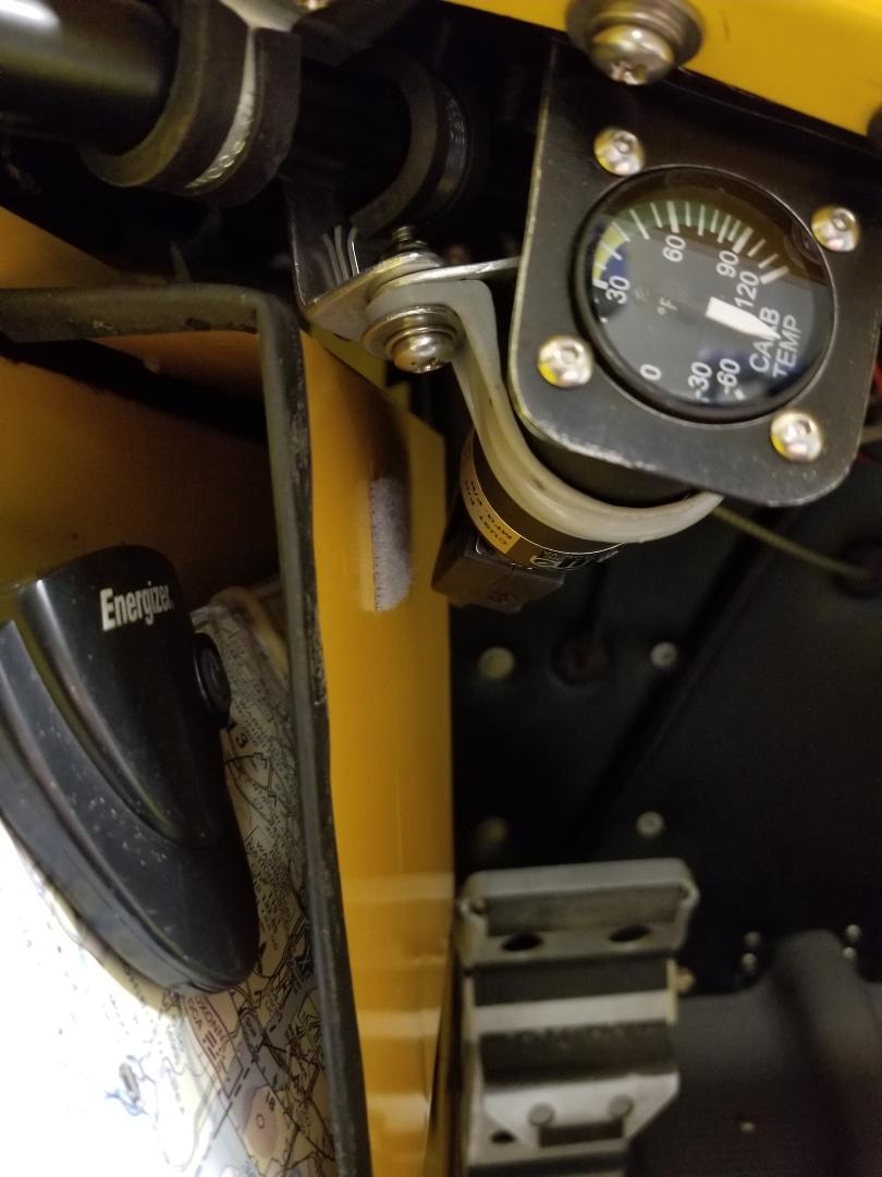
Below is the installed gauge--lower left.

Installation of the temp probe in the carb was straighforward. Pic below is the carb "before" showing the small "plug" that has 1/4-28 straight threads.

This pic shows the plug removed with a surrounding smooth surface. The probe comes with a copper washer that is sure to seal well against this surface.

Next is the probe installed, sealed with the new Permatex combo thread sealant locker compound--like anerobic thread sealant and blue loctite combined. Used on both sides of washer as well as threads, then safety wired.

Here is a pic using my DEPSTECH Borecope (with 90 degree mirror) of an upward view of the carb throat.

Finally, after running probe wires carefully back to firewall (thru a heat resistant fiberglass "conduit" sleeve) and covering the wires with heat shrink tubing as they pass thru grommet, I wired to the DB9 connector for the gauge. Power was supplied from the 10 amp rated 16 ga "Ext Bus" supply using a 1 amp fuse for the gauge. (This Bus also supplies power for the stall warning and electric trim.) Ground was to the left side ground bus on the support tube. I used 22 ga. uninsulated crimped ferrules. The probe wires were 22 ga. I used 20 ga red power and green ground, but these just fit into the 22 gauge ferrules that were the largest size the DB9 connector would accept. (I provided a 20 inch "service loop" so I could perform the work "on the seat" rather than with my head under panel. I did not provide for a disconnect at the carburetor to minimize resistance--will install a molex connector when/if I have to remove carb or engine.)

Tests show the gauge indicates carb temp accurately. Keep in mind the gauge is measuring air temp before the throttle plate, and practically is as much a measure of the temperature of the carburetor as the air, so there may be a lag between changes in air temp after the venturi and what the gauge reads.
Also remember that running full OR partial carb heat allows "unfiltered" air into the carb. Full carb heat via the "muff" on the #1 cylinder exhaust pipe (same pipe as EGT temp probe). Partial carb heat via both the "muff" and from another inlet source--essentially the engine cowl just below the carb. (I generally turn carb heat off on short final to insure all air goes thru the air filter when I am landing and ground taxing.)
No comments:
Post a Comment